OEM Annunciators Replace Reproduction Korrys in Main Instrument Panel (MIP)
/There can be little doubt that OEM annunciators shine far brighter than their reproduction counterparts. The korrys are lit during the lights test. OEM Flaps gauge yet to be installed
A task completed recently has been the replacement of the reproduction annunciators located on the Main Instrument Panel (MIP) with OEM annunciators.
The reason for changing to OEM annunciators was several-fold. First, anything OEM is superior to a reproduction item. Second, I wanted to reproduce the same korry annuciation lighting observed in the OEM panels in the center pedestal, fire suppression panel, and when fitted, the forward and aft overhead panels. Additionally, it was also to enable the push-to-test functionality and to provide better illuminance during daylight. Some reproduction korrys are not that bright when annunciated and are difficult to see during the day.
This post will explain the anatomy of the annunciators that are fitted to the Main Instrument Panel (MIP). It will also detail how the annunciators are wired and configured in ProSim737, and provide incite into some of the advantages and functionality that can be expected when using OEM annunciators.
The individual indexing can be observed on the top surface of the upper assembly (3 groves). To separate the two assemblies a hex screw must be used to loosen the hex screw located inside the brass-coloured circular fitting. Note that this is a new style LED korry which does not support the older incandescent bulbs
Anatomy of a Annunciator (Korry)
An annunciator is a light which is illuminated when a specific function occurs on the aircraft. Annunciators are often called by the generic name ‘Korry’, as Korry is the registered trademark used by a company called Esterline that manufactures annunciators for the aero and space industry.
There are two types of annunciators used in the Boeing aircraft, the 318 and the 319 which are either a Type 1 or Type 2 circuit.
The 318 and 319 Korrys are not interchangeable. Each Korry has a different style of bulb, differing electrical circuits, and a different method of internal attachment (captive hex screw verses two blade-style screws). The only similarity between the 318 and 319 korrys is that the hole needed to house the korry in the MIP is identical in size - .440” x .940”. The 318 Korry replaced the 319 Korry.
The circuit type refers to the electrical circuit used in the Korry. Both circuit types require a ground-controlled circuit to turn it on, however, Type 1 circuits are ground-seeking while Type 2 circuits are power-seeking. Visually (when installed to the MIP) the 318 and 319 korrys are indiscernible.
Annunciators have five parts that comprise:
(i) The lower assembly and terminals (usually four terminals in number);
(ii) The upper assembly;
(iii) The outer housing/sleeve which has a lip to allow a firm connection with the MIP;
(iv) The push-in light plate which includes the bulbs; and,
(v) The legend, which incorporates a replaceable coloured lens.
The four terminal connections on the rear of each annunciator are specific to the functionality of the unit. Each will exhibit a differing circuit dependent upon its function. Likewise, each annunciator is individually indexed to ensure that the upper assembly cannot be inadvertently mated with the incorrect lower assembly.
Annunciators typically are powered by 28 Volts, use two incandescent ‘push-in style’ bulbs, and dependent upon the korry’s function, may have a light plate coloured amber, white red or green. The legend is the name plate, and legends are usually laser engraved into the light plate to ensure ease of reading. The engraved letters are in-filled with colour to allow the printing to stand out from the light plate’s lens colour.
Specialised Korry
The Boeing 737 aircraft uses a Korry, a type 318, that is slightly different to the standard Korry. This Korry enables the functionality for the BELOW G/S – P-Inhibit function.
The Type 318 differs from other korrys used in the MIP in that it has a dry set of momentary contacts which are controlled by pressing the light plate. Pressing the illuminated light plate extinguishes the annunciator and cancels the aural ‘Below Glideslope’ caution.
Reproduction Verses Original Equipment Manufacture (OEM)
The four biggest differences between reproduction and OEM annunciators are:
(i) The ability to depress the light plate in the OEM unit for Push-To-Test function;
(ii) The ability to replicate specific functions, for example the Below G/S P-Inhibit korry;
(iii) The hue (colour) of the lens and crispness of the legend; and,
(iv) The brightness of the annunciator when illuminated (5 volts verses 28 volts).
Reproduction Korry Shortfalls
Two areas lacking in reproduction units is the brightness of the annunciator when illuminated, and poorly defined legends.
For the most part, reproductions use 5 volts to illuminate two LEDS located behind the lens. Whilst it is true that the use of LED technology minimises power consumption and heat generation, the brightness of the LEDS, especially during the day, may not be as bright as the two 28 volt incandescent bulbs used in an OEM annunciator. Moreover, 5 volts does not allow the successful use of DIM functionality.
It is unfortunate that many lower priced annunciators also lack well defined engraved lens plates making the ability to read the annunciator legend difficult at best.
Shortfalls notwithstanding, most high-end reproduction annunciators are of high quality and do the job very well.
Table 1: quick reference to determine the main differences between OEM and reproduction annunciators. Note that the appearance of the annunciator can alter markedly between different manufacturers of reproduction units

Installation, Interfacing and Configuration of OEM Annunciators
Replacing a reproduction annunciator with its OEM counterpart is straightforward if the Main Instrument Panel (MIP) has been produced 1:1; however, reproduction MIPs are rarely exactly 1:1 and in all probability you may need to enlarge the hole that the annunciator resides. If this is the case, ensure you use a fine-grade aluminum file and gentle abrade the hole to enlarge it. When enlarging the hole, ensure you continually check the hole size by inserting the korry – if the hole is enlarged too much, the korry will be loose and will require additional methods to secure to the MIP.
korry system 318 type 1
Disassembling a Korry
It is important to understand how to unassemble the annunciator.
First, the light plate has to be gently pried loose from the upper assembly. Once this is done, the upper and lower assemblies must be separated to allow the outer/sleeve to be removed. The Type 318 annunciators have a hex screw, located in the lower assembly unit, which needs to be loosened with a 5/64th hex wrench to allow separation, while the Type 319 annunciators are secured by two standard screws that require a small blade screwdriver.
Once the two parts are separated, it should be noted that the upper assembly has a flange at the forward end; this flange enables the annunciator to be firmly connected to the MIP.
Attaching a Korry to the MIP
Is your MIP 1:1 and will it fit OEM korrys without further to do? Click the diagram to see the dimensions of korrys (with thanks to Mongoose for diagram)
Insert the upper assembly into the MIP flange facing forward. Next, slide the housing over the rear of the mechanism from the rear of the MIP. Rejoin the lower section and tighten the hex screw. If the MIP is 1:1, the annunciator should now be firmly secured to the MIP wall. The light plate can now be pushed into the mechanism.
If the annunciator does not fit firmly into the MIP, it can be secured by using silastic or a glue/metal compound. (I do not recommend this. It is best to ensure the hole is the correct size or a tad too small. This will guarantee that the annunciator will have a firm fit).
Provided the mechanism is not faulty or does not break, the chance that it will need to remove it is very remote. If the bulbs fail, they are easily replaced as they are contained within the light plate.
Wiring - Procedure
Wiring the MIP annunciators is a convoluted and repetitious process that involves daisy-chaining the various annunciators together. Because wiring is to and from four terminals, it can be difficult to remember which wire goes where. As such, it is recommended to use coloured wire, label each wire and keep meticulous notes.
Each annunciator has four terminals located on the rear of the unit that corresponds to:
(i) Positive (28 volts);
(ii) Logic for the function of the korry;
(iii) Lights test; and,
(iv) Push-To-Test.
To crosscheck the above, each Type 2 korry has a circuit diagram stenciled on the side of the assembly.
Figure 1: A schematic of the three types of korrys used in the Boeing 737. The left diagram is from the 318 push to inhibit korry (diagram copyright David C. Allen
For the OEM korrys to function correctly, they need to be connected with an interface card (I/O card). An example of such a card is a Phidget 0/16/16 card.
(i) Designate the annunciator closest the I/O card and power supply as the lead annunciator (alpha).
(ii) Terminal 1 and Terminal 4 are the power terminals for each korry. Connect to the alpha korry the positive wire from the 28 Volt power supply to terminal 1 and the 28 Volt negative wire to terminal 4. The wires from these two terminals are then daisy-chained to the identical terminals on the other korrys in the system.
(iii) Terminal 2 controls the logic behind the function for each korry. A wire must connect from terminal 2 of each korry to the output side of the I/O card. To close the loop in the I/O card, a wire is placed from 28 Volts negative to the ground terminal on the card (input).
(iv) Terminal 3 controls the logic behind the light test toggle. A wire is daisy-chained from terminal 3 of the alpha korry to all other korrys in the system. A wire is then extended from the final korry to the lights test toggle switch. This switch has been discussed in detail in a separate post.
Quite a bit of wire will be needed to connect the thirteen or more annunciators and it is a good idea to try and keep the wire neat and tidy by using a lumen to secure it to the rear of the MIP.
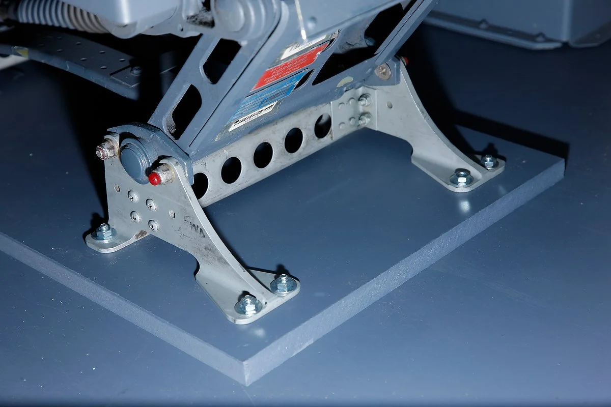
Mounting and Brackets
Every simulator design is different, and what is suitable for one set-up may not be applicable to another.
The I/O card that is used to control the MIP annunciators is mounted within the System Interface Module (SIM). To this a straight-through cable is securely attached that connects to a D-Sub connector mounted on an aluminum bracket. The bracket and two terminal blocks are strategically mounted on the rear of the MIP and enable the various wires from the korrys to connect with the straight-through cable.
Interfacing and Configuration Using ProSim737
To interface the annunciators, follow the directions on how to wire your I/O card.
This article provides information on the Phidget 21 Manager (software) and how a Phidget interface card is used.
If the annunciators have been correctly daisy-chained together, only the wires from terminal 2 of each korry will need to be connected to Phidget card. When power is applied, the Phidgets software will automatically assign outputs to any device (korry) attached to the 0/16/16 card.
To determine the digital output number for each annunciator, open the Phidgets 21 Manager, push the light plate on a chosen annunciator and record the allocated output number. The output numbers are used by ProSim737 to allocate that annunciator to a specific software command line.
Configuring the MIP annunciators in ProSim737 is a two-step process. First, the annunciator must be assigned as a switch (for the puhs- to-test function to operate), then as an indicator (for the annunciator to illuminate). Before commencing, check that Phidgets have been assigned in the driver section of the configuration section of the main ProSim737 menu.
Open the configuration screen and select switches and scroll downwards until you find the appropriate switch that corresponds to the annunciator. Assign this switch to the output number assigned by the Phidgets software (If you have multiple Phidget cards installed ensure the correct card is assigned).
After this has been completed, continue the configuration process by assigning each annunciator to the appropriate indicator in the configuration/indicators section.
Lights Test
A lights test is used to determine whether all the annunciators are operating correctly. A lights test can be accomplished two ways.
The first method is to press the light plate of an annunciator which operates a momentary switch that causes the light to illuminate (push-to-test). This is an ideal way to determine if an individual annunciator is working correctly.
The second method is to use the MIP toggle switch. Engaging the toggle switch to the on position will illuminate all the annunciators that are connected to the toggle switch. This is an excellent way to ensure all the annunciators are operational and is standard practice before beginning a flight.
It should be noted that for all the annunciators to illuminate, each korry must be connected to the toggle switch.
An earlier post explained the conversion and use of a OEM Lights Test Toggle Switch.
The fire suppression panel annunciators are also korrys. Like their MIP sisters, the korrys are very bright when illuminated as they are powered by 28 volts
Korry Systems
This post has discussed the main annunciators on the MIP which is but one system. Other systems include the annunciators for the forward and aft overhead annunciators, fire suppression panel and several other panels.
To connect additional systems to the enable a full lights test to be done, an OEM aircraft high amperage relay can be used.
OEM multi-relay device. The relay from a Boeing aircraft is not necessary; any aircraft relay will suffice. It's wise to choose a relay that has multiple connection posts as this will enable different systems to be connected to the relay. The relay is easily fitted to the rear of the MIP or to the inside of the center pedesta
Depending upon the type of relay device used (there are several types), it may be possible to connect up to three systems to the one relay. This is made possible by the OEM toggle switches unique multi-segment system, and the ability of the relay to handle high amperage from multiple aircraft systems.
A benefit of using an OEM relay is that it provides a central point for all wires from the various systems to attach, before connecting to the lights test toggle switch. Note that 28 volts bmust be connected directly to the relay for correct operation.
The relay will, depending upon the throw of the toggle switch (lights test), open or close the circuit of the relay. Opening rhe relay circuit (when the light test toggle is thrown) enables 28 volts to flow through the relay and illuminate any annunciators connected to the system.
Availability
The Korrys originally were used in British Airways 737-400 Airframe 25843 G-DOCM (copyright Aero icarus)
Fortunately, apart from a few functions, there is little difference between older style annunciators used in the classic series airframes and those used in the Next Generation aircraft - an annunciator is an annunciator no matter from what airframe (100 series, Classic or Next Generation).
Annunciators are relatively common and are often found ion e-Bay. However, to acquire a complete collection that is NG compliant can be time consuming, unless a complete panel is purchased and the annunciators removed.
Lineage
The annunciators used in the simulator came from a B737-400 airframe. This aircraft - serial number N843BB and construction number 25843 had a rather interesting lineage.
It began service life in March 1992 with British Airways as G-DOCM before being transferred to Fly Dubai and Air One in 2004. Late 2004 the airframe was purchased by Ryan International and the registration changed to N843BB. Between 2005 and 2010 the aircraft was leased to the Sundowner LCC who at the time was contracted to the US Dept. of Justice. The aircraft was returned to Ryan International mid 2010 and subsequently scrapped.
Acronyms
OEM - Original Equipment Manufacturer (aka real B737 aircraft part)