How to Customise Text When ProSim737 Opens in MSFS-2020

JAL 737-800 departing Toyama (RJNT) Japan

A somewhat annoying aspect of using ProSim737 in MSFS-2020 is that when MSFS initiates the loading of the 737 livery (by pressing Fly Now) a long message is displayed across the lower screen.

While the displayed text serves a purpose, it becomes redundant after repeated viewings.

Many users have asked if it is possible to remove this message or replace it with customised text. 

The displayed text:

  • This version of the ProSimB738 plane MUST be used under the "MODERN" mode of the MSFS flight model! 

  • In a couple of years the ‘MODERN’ mode in MSFS will become a legacy one. 

  • ProSim Training-Solutions presents you the MSFS version of our B738. There are functions not yet completely working with our plane due to present limitations in the simulator. 

  • Visit us at www.prosim-ar.com for our award winning solutions for the A320 & A320Neo and the MAX8. 

  • You have to disable all related control-axes in MSFS and assign them only in ProSim.  The ProSim 738 offers two winglet configurations to use.

Steps to Edit the Aircraft.cfg File

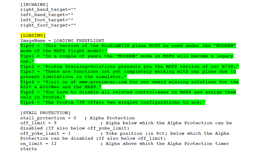
To remove or alter this text, you must edit the aircraft.cfg file. This file is part of the Visual Flight Model.  The aircraft.cfg file can be found at:

Community Folder/Aircraft/Prosim-B738-v2023/Simobjects/Airplanes/Prosim-b738-2023.

  1. Create a backup of the aircraft.cfg file.  You can copy the folder and rename it to something like aircraft_backup.cfg, though you can use any name you prefer. 

  2. Open the aircraft.cfg file in a text editor and scroll to the section named [Loading].

  3. Modify or delete the lines named Tips0 through Tips6

    • To remove the displayed message, delete the lines labelled Tips0 through Tips6. This will prevent any message from being displayed.

    • To replace the text, edit the content of Tips0 through Tips6.  For example, to display only one line of custom text, edit Tips0 and delete the remaining lines.

  4. Remember to include the quotation marks each side of your written entry.

In my simulator I have removed the entries and replaced them with: Tips0 = "Aircraft Loading (Boeing 737-800) - Flaps 2 Approach"

Documenting Edits  

After making changes to the aircraft.cfg file, it is good practice to document them at the top of the file. Use // before adding comments, as lines prefixed with // are ignored by the computer system.  

For example, // Edited on 20-11-2024: Removed default loading tips and added custom message.  

Important Point:

  • If the Visual Flight Model is reinstalled or updated, the aircraft.cfg file will be replaced. You will need to reapply your edits. To simplify this process, keep a copy of your modified file to quickly copy and paste your changes into the updated file.  

Final Call  

Editing the aircraft.cfg file enables you to remove or customize the message to better suit your preferences, however, although this is a straightforward task, it is important to create a backup of the file prior to making any changes.  

BELOW: Gallery showing aircraft.cfg edits.

Flight Sim Live Traffic Liveries (FSLTL) - Short Review

FSLTL ANA and JAL at Toyama (RJNT), Japan

Those who have used flight simulator for many years will recall the days when you flew alone, with no other aircraft except a few poorly defined airliners, or a Cessna or two parked at the airport. Flight simulator has come a long way since then, and today it’s possible to fly on-line with several other user-piloted aircraft, or at the very least have several well-made AI (artificial intelligence) aircraft in the sky around you.

As simulator AI evolved, so did the number of AI programs and add-ons that were available, with some packages providing real world airline schedules and user adjustable aircraft liveries. Needless to say as AI grew, so did the complexity in installing and running these programs. Unless you enjoy the complexities of software, I dare say that you want an AI package that works, is easy to use, and runs in the background, allowing you to fly the simulator and not continually have to tinker with AI. FSLTL is such a program.

This is a short review, meaning I am not going to delve into the intricacies of FSLTL. The developer has included a very easy to understand manual and a video; to rehash what is already written in the manual is counter productive to the product.

General

FSLTL (Flight Sim Live Traffic Liveries) is a free, easily configurable AI program that can be turned on or off at will and runs in the background. The program is VATSIM compliant and interacts with the default Air Traffic Control in MSFS-2020 and AI Air Traffic Control programs, such as Beyond ATC and Say Intentions.

FSLTL does not use imaginary flight schedules. Rather, it extrapolates flight data from FlightRadar 24 (FR24) and replicates these flights in flight simulator using the appropriate aircraft types and liveries. Therefore, when you see an airbus A380 taking off from Adelaide International (YPAD) the AI is reflecting the actual flight schedule of the real airline. The real time flight information from FR24 is pinged every 20 seconds so the replication is not exactly real time, but it is very close.

Although there is no reason to use other AI traffic, FSLTL has the capability to also incorporate AI aircraft models and liveries from third party providers (for example, Just Traffic). The aircraft type and liveries used by FSLTL come from a variety of sources with FAIB (FSX AI Bureau) creating many of the models and liveries.

FSLTL is updated from time to time with new aircraft and liveries.

Installation

Installation of the program is very straightforward. An installer (Fly-By-Wire installer) is downloaded to your computer from the FSLTL website. After running the installer, you select the components you want to use. You will need the Traffic Injector and the Traffic Base Models package. The base model package is quite large; therefore, be certain there is appropriate space in your computer to store the files. Both the traffic injector and base model package must be installed into the community folder of MSFS-2020. If you wish to install these items outside of the community folder then this can be done; however. the files will need to be linked to the community folder using a program such as MSFS add-ons linker.

Important Point:

  • FSLTL uses simconnect. At a minimum, VC++ Redist 2015-2022 x64 must be installed on your computer.

FSLTL Traffic Injector User Interface

Traffic Injector and User Interface (UI)

The traffic injector is the .exe file that starts FSLTL and injects the traffic into flight simulator. A shortcut can be made to this file and stored anywhere you wish: on your desktop, in the menu bar, or it be added to a batch file to automatically load when flight simulator is started. The base models package is only a folder with the various models. It requires nothing be done to it other than placing the folder in the correct location.

The traffic injector user interface (UI) can be accessed either by selecting the icon from the inflight menu system in MSFS-2020, or as discussed by a standalone .exe icon. Opening the User Interface enables the user, amongst other things, to streamline the program and control the number of aircraft being spawned at any one time, either in the air or on the ground. The UI also can re-spawn AI aircraft, set the distance that AI aircraft can be spawned, or remove AI aircraft during the final landing phase. This can be beneficial when landing in airports that have high density traffic.

In my simulator, I have the FSLTL .exe icon in the menu bar. After loading flight simulator and ProSim737, I click the icon and within 1 minute AI traffic has been spawned.

File structure to open the preference panel for FSLTL

Traffic Injector Preferences

The traffic injector user interface can be changed to suit individual preferences. This is done by opening the user interface configuration file located at %APPDATA%\ fsltl-traffic-injector and selecting the fsltl-trafficinjector-config.json file. The .json file can be opened in a text editor by right clicking the file. Once the file is open you will note the various preferences that can be changed and saved.

Frame Rates and Resources

With normal use, with the exception of hard drive space to store the base models package, FSLTL uses minimal computer resources and does not affect frame rates. If you decide to have the maximum number of aircraft at an airport, in flight at varying distances, and also use other third party AI traffic, then there is a slight hit to frame rates.

Aircraft Types and Liveries

FSLTL AI aircraft have been built using glTF models for better performance, reduced stutters, and CTD avoidance. Apart from the visual appeal of looking at a well constructed model, this improves AI ground roll during take-off and landing. it also enables the display of custom lighting, contrails, heat haze and other effects, including interaction with jetways and ground services.

The base model package includes over 1900 liveries and includes all major airline aircraft types and light aircraft. At the time of writing, military aircraft and helicopters are not included.

Downsides and Known Issues

There are several known limitations with MSFS-2020 that can cause issues with AI traffic. Thankfully, none of these shortfalls relate to resource usage and frame rates. FSLTL have listed the known issues in their on-line manual.

Pink Liveries

One particular problem that did occur to me, was that several AI models were displayed as checkered designs or were coloured hot pink (rather than the correct airline livery). Whenever this occurs, it is an indication of a problem concerning the aircraft’s texture folder, or the file has been corrupted.

In my case, the problem was that the aircraft type in question (the Beechcraft King Air) was not installed into MSFS-2020. In an effort to streamline my set-up, I had deleted various aircraft types and models that I did not use. Once I reinstalled the King Air aircraft type (not the various liveries) using the content manager, the pink colours disappeared and I was presented with the correct livery (in this case a Royal Flying Doctor Service livery).

If this issue persists, and you have the aircraft types installed into MSFS-2020, the next step is to determine where the problem lies. It is relativity easy to troubleshoot this problem.

  1. Open MSFS-2020 in developer mode.

  2. Navigate to the debug/console tab (at the top of the screen).

  3. Open console and check through the various listings.

You are searching for any listings which have been tagged in yellow. As you scroll through the listings, you will eventually find the aircraft type that you noticed the problem with (checkered design or hot pink colour). This is the aircraft file that potentially has a corrupted texture file. Note the aircraft type, and then navigate to the MSFS-2020 file structure (msfs/Official/OneStore/Asobo Aircraft folders/SimObject/Airplanes/aircraft folder in question/Textures).

Open the Asobo aircraft files and scroll through the listings until you find the folder that contains the files for the aircraft in question. Open the aircraft folder and check that the appropriate texture files are included. Each aircraft should have a number of texture folders. For example, texture, texture01, texture02 and texture03. Sometimes the texture folder (no number) is missing. If this is the case, delete the aircraft folder, run MSFS-2020 and allow the program to reinstall the aircraft from the cloud. This should resolve the problem.

Final Call

I have used this program since I began using MSFS-2020. Previously, I used a number of payware AI programs which always seemed to require me to tweak or tinker with airline schedules. These programs also had a relatively steep learning curve. FSLTL works out of the box and does exactly what it says it will do, with minimal fuss - and it will cost you nothing other than a donation to the developer if you like the program.


737-800 Landing Procedure


737-800 Transocean Air on finals Komatsu (RJNK) Japan © redlegsfan21 from Vandalia, OH, United States, JA8991 (24643740539), CC BY-SA 2.0

In this article I will discuss the techniques used to land the 737-800 aircraft.  

The choice of landing approach is often influenced by considerations such as the specific criteria required for the approach, the desired level of automation, and the individual pilot's preference and technique. Regardless, the method used to actually land the aircraft is similar in all approach types.

The first part of the article discusses techniques used in the approach, descent and landing.  This is followed by a short recap regarding situational awareness, which is critical in any approach and landing.  At the end there is a downloadable step guide explaining the procedure to land the 737-800.

Discussing landing technique without addressing the approach is counter intuitive.  As such, a generic style approach has been ‘loosely’ used to provide a frame of reference.  Furthermore, in an effort to ensure clarity and provide sufficient context, certain information discussed in previous articles may have been reiterated. I purposely have not discussed the requirements for a specific approach type, nor have I included, or discussed detailed checklists.

I have attempted to include as much information as possible which, can have a tendency to make the subject appear complicated; it is not complicated.  Carefully read the information and note that:

  • There is a considerable variability in how the 737 is flown.  Certainly there are wrong ways to do things, however, there is no single right way to do it; and,

  • Airline policy often dictates how an approach is flown based on whether it is a Precision Approach or a Non Precision Approach.

Generally speaking, an approach can be segregated into three segments:

  • The initial approach;

  • The landing approach (descent phase); and,

  • The final approach (landing phase).

Discussion

Initial Approach

Technically, the approach starts when entering the traffic pattern, terminal airspace or at the Initial Approach Fix (IAF), which is published on the approach chart.  However, not all approaches have an IAF, and some require that the airplane be vectored to the final approach course by Air Traffic Control.   Even if there is an IAF, ATC may still decide to vector a plane to the final approach course to make more efficient use of airspace.

Prior to reaching the IAF, or receiving vectors to final, the flight crew should have prepared the aircraft for approach, briefed the crew, and begun to slow the aircraft.  Workload increases considerably during the descent; therefore, it is sensible to complete whatever can be completed prior to the descent point. Descent planning and preparation is usually completed before the initial approach segment begins, which is approximately 25 miles from the runway.

Important Points:

  • Approach planning should be completed prior to the descent point; preferably completed before reaching the IAF.

  • In general, unless indicated otherwise, a flight crew will want the aircraft at approximately 3000 ft AGL no less than 10 NM from the runway.

Landing Approach

The landing approach begins at the Final Approach Fix (FAF). However, the terminology will differ depending upon the type of approach being flown. For the purposes of this article, I will use the term Final Approach Fix (FAF) to indicate the decent point.

Precision and non precision approaches will have the required descent point indicated on the approach chart, which will differ depending upon the approach type selected.

When reaching the FAF, the aircraft will in all probability be controlled by the autopilot with guidance being controlled by LNAV and VNAV (or another pitch/roll mode).

Depending on the type of approach chosen, the aircraft will be transitioning from level flight to either a step-down approach (SDA) or a continuous descent approach (CDA).  Step-down approaches are rarely used today; continuous descent approaches are more the norm.  A CDA, unless otherwise stated on the approach chart, uses a 3 degree glide path.

If you examine the two approach charts (click to enlarge) you will note that the VOR 06 approach shows the descent point at HERAI at 1455 ft AGL. The point is marked by a Maltese Cross and is also shown as the FAF (Final Approach Fix) in the distance legend. Also note that both a step down and a continuous approach is displayed on the chart. In the second chart (ILS 06) the descent point is shown as a LOC (localizer) at 1964 ft AGL and the FAF is noted in the distance legend. Note the chart is also annotated IF (Initial Fix). Different charts will display different annotations.

The reason for showing these two charts, is to demonstrate that the descent point and distance from the runway to begin the descent, will change depending upon the approach type selected from the FMC (assuming an approach from the FMC is used).


RJNK VOR 06


RJNK ILS 06


‘Loose’ Recommendation

As I have already mentioned, there are multiple ways to approach and land the 737; ask several pilots and each opinion will be slightly different. Generally speaking, without alternate guidance from Air Traffic Control or an approach chart, the following recommendations should be adhered to. The aircraft should begin descent to the runway at:

  • Approximately 10 NM from the runway;

  • At approximately 3000 ft AFE;

  • Have flaps 1 extended; and,

  • Be flying at as airspeed no greater than 200 kias.

If the aircraft is following the ILS approach course, it is better to intercept the ILS glideslope slightly from below rather than above. Intercepting the glideslope from below enables greater control of airspeed.

Speed Management

Speed management is probably the most critical factor during any approach.  A common saying is ‘you have to slow down to get down’. This said, it is a bit of a conundrum. The airline wants its pilots to optimise the aircraft’s airspeed for as long as possible, because this means less fuel use, less noise, and lower engine operation times.

Slowing the 737-800 aircraft is not easy when the aircraft is descending, so it is a good idea to begin to reduce the airspeed when the aircraft is in level flight prior to beginning the descent. The thrust levers should be brought to idle (idle thrust or near to) and the airspeed allowed to decay to the flaps UP maneuvering speed.  The flaps UP indication is displayed on the speed tape in the PFD. If speed reduction is initiated before reaching the IAF, the airspeed will decay naturally without use of the speedbrake. 

Important Points:

  • It requires approximately 25 seconds and 2 NM to decelerate the 737-800 from 280 kias to 250 kias, and it will take a little longer decelerating from 250 kias to 210 kias. More simply written, it takes approximately 1 NM to decrease airspeed by 10 kias in level flight.

  • The aircraft should begin slowing at 15 NM from the airport to be at 10 NM at 3000 ft AFE at a speed of approximately 190-200 kias with flaps 1 extended.

  • The aircraft’s airspeed should be reduced to flaps UP maneuvering speed no later than the IAF.

Speedbrake and Flaps Use

The transition from level flight to descent will be much easier, with less need to use the speedbrake, if the aircraft is already at a lower airspeed prior to the descent.  If the speedbrake must be used, try to minimise its use at and beyond flaps 5.  With flaps 15 extended the speedbrake should be retracted. The speedbrake should not be used below 1000 ft AGL. 

Although the speedbrake is designed to slow the aircraft, its use causes increased inside cabin buffeting and noise, decreases fuel efficiency, and can lead to unnecessary spooling of the engines; these factors are exacerbated if the aircraft is descending and travelling at a slower speed. If the speedbrake is to be used during the descent, lower the speedbrake (clean configuration) before adding thrust, otherwise thrust settings will need to be adjusted.

It must be stressed that using the flaps to slow down by creating more drag is not good technique and is frowned upon.  Additionally, continual use of the flaps to slow an aircraft can cause damage to the flaps mechanism over a period of time - adhere to the flaps extension schedule (discussed shortly).

If the aircraft’s speed is too high and the approach is too fast, lowering the landing gear early is an excellent way to slow the aircraft, but bear in mind that this will also increase drag, generate noise, and increase fuel consumption.  This should only be done as a last resort.

Important Points:

  • Whenever the speedbrake is used, the pilot flying should keep his hand on the speedbrake lever. This helps to prevent inadvertently leaving the speedbrake lever extended. 

  • Flaps, in principle, are not designed to slow the aircraft (although their drag does, by default, slow the aircraft); the aircraft’s pitch, thrust, and the use of the speedbrake do this.

Flaps Extension Schedule

All to often novice virtual flyers do not adhere to the flaps extension schedule.  Extending the flaps at the incorrect airspeed can cause high aircraft attitudes, unnecessary spooling of engines, excessive noise, and increased fuel consumption which can lead to an unstable approach. If the flaps are extended at the correct airspeed, the transition will be relatively smooth with minimal engine spooling.

The correct method to extend the flaps is to extend the next flaps increment when the airspeed passes through the previous flaps increment.  For example, when the airspeed passes through the flaps 1 indication, displayed on the speed tape in the PFD, select flaps 2.

The 737 has 8 flap positions excluding flaps UP.  It is not necessary to use all of them.  Flight crews will often miss flaps 2 going from flaps 1 to flaps 5. Similarly, flaps 10 may not be extended going from flaps 5 directly to flaps 15 and flaps 25 maybe jumped over selecting flaps 30. Flaps 30 in the norm for most landings with flaps 40 being reserved for short-field landings or when there is minimum landing distance. In the case of using flaps 40, flaps 25 is normally extended.

My preference is to use flaps 25 as it makes the approach a little more stable. However, if you are conducting a delayed flaps approach, selecting flaps 25 may not give you enough time to extend flaps 30 or 40 and complete the landing checklist before transitioning below ~ 1500 feet AGL.

Flaps 40

The use of flaps 40 should not be underestimated, as aircraft roll out is significantly reduced and better visibility is afforded over the nose of the aircraft (because of a lower nose-up attitude). Because the landing point is more visible, some flight crews regularly use flaps 40 in low visibility approaches (CAT II & III). If the aircraft’s weight is high, the runway is wet, or there is a tailwind, flaps 40 is beneficial. A drawback to using flaps 40, however, is the very slow airspeed (less maneuverability) and higher thrust required. For this reason, if there are gusting winds it is better to use flaps 30.

Advantages

  • Less roll out;

  • Better visibility over the nose of the aircraft due to lower nose-up attitude;

  • Less wear and tear to brakes as the brakes are generating less heat (faster turn around times);

  • Less chance of a tail strike because of slightly lower nose-up attitude during flare;

  • More latent energy available for reverse thrust (see note); and,

  • Helpful when there is a tailwind, runway is wet, or aircraft weight is high.

Disadvantages

  • Increased fuel consumption (negligible unless flaps 40 are extended some distance from runway);

  • Increased drag equating to increased noise (flaps 40 generates ~10% additional thrust); and,

  • Less maneuvering ability.

NOTE: When the aircraft has flaps 40 extended, the drag is greater requiring a higher %N1 to maintain airspeed. This higher N1 takes longer to spool down when the thrust levers are brought to idle during the flare; this enables more energy to be initially transferred to reverse thrust. Therefore, during a flaps 40 landing more energy is available to be directed to reverse thrust, as opposed to a flaps 30 landing.

Important Point:

  • Correct management of the flaps is selecting the next lower speed as the additional drag of the flaps begins to take effect.   


TABLE 1: Flaps Extension Table. The table does not include flaps 2, 10 & 25. © JAL-V


Maneuvering Margin

The maneuvering margin refers to the airspeed safety envelope in which the aircraft can be easily maneuvered.  This is pertinent during descent, as when the aircraft slows down its ability to maneuver is less than optimal.  An adequate margin of safety exists when the airspeed is at, or slightly above the speed required with the flaps extended.  This is displayed as a white carrot in the speed tape in the PFD. 

Procedure Turns

A procedure turn (PT) is a maneuver to perform a course reversal to establish the aircraft inbound on an intermediate or final approach course. They are often used when flying a VOR approach. If carrying out a procedure turn to intercept the localizer and FAF, try to be at flaps 5 maneuvering speed, with flaps 5 extended, prior to localizer capture and descent.

Pitch and Power Settings (Fly By The Numbers)

Whenever the aircraft is flown by hand (manual flight), pitch and power settings become important.  A common method used by experienced pilots is to fly by the numbers.

The term fly by the numbers is when the pilot positions the thrust levers commensurate to a desired %N1 pursuant with the aircraft’s attitude, configuration and speed.  The %N1 is based on aircraft weight and is displayed in the EICAS.   If the published figures are not available, a reasonable baseline %N1 to begin with is around 55%N1.  Aircraft with heavier weights will require higher thrust settings while lower thrust settings will be needed for lighter weights.  The thrust setting is arbitrary and %N1 will need be fine-tuned with small adjustments.

Once the thrust has been set, always allow the thrust to stabilise for a few seconds and ensure that both thrust levers display an identical %N1.  If you fail to do this, and the thrust settings are slightly offset (despite the thrust levers being beside each other) the aircraft will turn in the direction of least thrust (asymmetric thrust).

During the descent, %N1 may be close to idle thrust, however, as the flaps are extended and the landing gear is lowered, the %N1 will need to be increased to counter the effects of drag. The approximate figure of %55N1 should be set immediately prior to the landing gear being lowered.

Important Points:

  • The %N1 is a baseline figure, the correct %N1 will depend on the weight of the aircraft and any wind component. 

  • Set %N1 immediately prior to lowering the landing gear and extending flaps 15.

It is almost miraculous that once the correct thrust has been set, the others numbers that relate to airspeed and rate of descent fall into place, and the aircraft will only require small incremental adjustments to maintain a 3 degree glide path.

Recommendation:

  • In order to gauge how the aircraft reacts during an approach, fly several automated approaches (the easiest to fly is the ILS Approach).  Observe the thrust settings (%N1) as you extend the flaps and lower the landing gear.  Note the numbers for the particular weight of the aircraft. 

Reaching the Initial Approach Fix (IAF)

As discussed above, the IAF will differ between approach types. The two most important aspects that should be completed just prior to reaching the IAF are:

  • The landing briefing and tasks completed; and,

  • The aircraft’s airspeed should be at flaps UP maneuvering speed, or at flaps 1 maneuvering speed.

Reaching the Descent Point (FAF)

Ideally the aircraft will be at flaps UP maneuvering speed no later than the IAF. If this is done, the transition from level flight to descent will be much easier. At the very latest, plan to be at, or just before the FAF at flaps UP or flaps 1 maneuvering speed.   If concerned that the airspeed is too fast, slow the aircraft to a speed that corresponds to the flaps 1 or flaps 2 indications displayed on the speed tape.   The airspeed will usually fall between 210-190 kias

The point at which the aircraft descends will depend on the approach type used, but If the aircraft’s airspeed has been managed appropriately, initiating the descent at the FAF is relatively straightforward.  During descent the aircraft should:

  • Have the thrust levers set to idle thrust (or near to);

  • Have an attitude of approximately 5 degrees nose-up;

  • Maintain a constant rate of descent (sink rate) between ~600-800 ft/min;

  • Be on a constant 3 degree glide path; and,

  • Not have a descent rate greater than 1000 ft/min. 

Important Points:

  • In some situations (for example, whether the aircraft is in level flight or is descending) to initiate the descent, it may be necessary to lower the attitude to below ~5 degrees nose-up, and then increase the attitude to counter any initial airspeed increase, until the appropriate rate of descent and glide path is established.

  • To aid in passenger comfort, steep descents with the aircraft’s nose below the horizon and pointing downwards should be avoided.

If you are uncertain to the glide path being flown, refer to the Flight Path Vector (FPV) in the PFD.

During the initial descent phase:

  • Speed is controlled by pitch; and,

  • Rate of descent is controlled by thrust.

As you transition to the final approach phase, this changes and:

  • Speed is controlled by thrust; and,

  • Rate of descent is controlled by pitch.

Model aircraft is used to visualise various approach and landing attitudes

The above dot points confuse many virtual flyers and trainees alike.  Rather than attempting to visualise this in your mind, use a small model airplane and position the model in a particular flight phase with the correct attitude.  After a while it will make sense and become second nature.

Descent

After initiating the descent in idle thrust and with the aircraft’s attitude set to approximately 5 degrees nose-up, the aircraft’s airspeed will slowly decay.  As the aircraft slows, match the airspeed to the flap indications on the speed tape.   The maximum airspeed during the descent should not exceed Vref +20 or the landing placard speed minus 5 knots – whichever is lower (Boeing FCTM, 2023). 

Vref +20 is indicated by the white carrot on the speed tape, which is displayed when Vref is selected in the CDU. 

Lowering the Landing Gear (General Rule)

A rule of thumb used by many flight crews in favourable weather conditions is to lower the landing gear and select flaps 15 at ~7 NM from the runway threshold.   At this distance, the aircraft’s altitude is ~2500-2000 ft AGL, and then, prior to reaching 1500 ft AGL, select landing flaps (25, 30 and/or 40).  This enables ample time to ensure that the aircraft is stabilised, and to complete the landing tasks and landing checklist. 

As an aid, flight crews typically will place a ring, displayed on the Navigation Display, at the distance that the landing gear is to be lowered. The ring, created in the CDU, provides a visual reference as to when to lower the landing gear. A ring is also often added at the IAF, or at 10 NM from the runway threshold.

Delayed Flaps Approach

Some airlines and pilots use less conservative distances, thereby minimising the time that the aircraft is flying with the landing gear lowered and flaps extended. A delayed flaps approach or minimum noise approach, will usually have the landing gear lowered and flaps 15 extended at 4 NM from the runway. Landing flaps will then be extended very soon after.

Delayed Flaps Approach - Caution

While lowering the landing gear and extending the landing flaps close to the runway threshold has positive benefits to the airline, and does limit the noise generated, it is not without its problems. Potential problems are:

  • If there is a landing gear or flaps failure, the aircraft is very close to the ground;

  • The landing checklist must be done quickly when concentration may be needed elsewhere (landing);

  • If the aircraft’s airspeed is too high, slowing down is difficult at this late time; and,

  • If windshear or other weather related events occur the aircraft is very close to the ground with minimal room to escape.

When the landing gear is lowered and the landing flaps are extended, the aerodynamics of the aircraft are significantly changed. The pilot must be prepared to adjust the flight controls (pitch and thrust) to maintain control; this is especially so when hand-flying the aircraft. Being in close proximity to the ground at this stage can amplify the risk of a ground strike should the pilot have difficulty adapting to the altered aerodynamics.

Lowering the landing gear and extending the flaps, at a distance of 7-5 nautical miles from the runway, provides additional time and a crucial safety buffer for the pilot to acclimate to the new aerodynamic conditions.

Important Points:

  • The 737-800 is renown for being slippery and difficult to slow down, which is why it is recommended to slow the aircraft prior to the FAF. 

  • A Rule of Thumb often used is: It takes approximately 3 NM to loose 1000 ft of altitude (assuming flaps UP maneuvering speed).

  • A delayed flaps landing should be attempted only in optimal weather conditions.

If you slow the aircraft prior to reaching the IAF, maintain the correct thrust settings to aircraft weight, and extend the flaps at their correct speeds, the descent and approach will usually be within acceptable limits. You will also not have to use the speedbrake.

Stabilised Approach

During the final approach the aircraft must be stabilised; if the approach becomes unstable and the aircraft descends below 1000 feet AFE in IMC, or 500 feet AFE in VMC, an immediate go around must be initiated.

An approach is considered stable when the following parameters are not exceeded:

  • The aircraft is on the correct flight path;

  • Only small changes in heading and path are needed to maintain the correct flight path;

  • The power settings for the engines are appropriate to the aircraft’s configuration;

  • The aircraft’s airspeed is no more than Vref +20 kias and not less than Vref (plus wind component); and,

  • The descent rate of the aircraft is no greater than 1000 ft/min (no special briefing).

Stability during an approach is made considerably easier if the aircraft:

  • Is travelling at the correct airspeed;

  • Is trimmed correctly for neutral stick.

  • The flaps are extended at the correct flaps/speed ratio;

  • The attitude (pitch) is correct; and,

  • The thrust settings are commensurate with the desired airspeed and rate of descent.

My preference is to have the aircraft stabilised with the landing check list completed by 1500 feet AFE. At this point, the autopilot and autothrottle are disengaged and the aircraft is flown manually. Although the handoff can be done later, doing it at ~1500 feet enables enough time to take control of the aircraft and make any final adjustments from automated to manual flight.

Important Point:

  • The height that an aircraft must be stabised is often dictated by airline policy. The height typically is between 1500-1000 feet AFE, but can vary between operators.

Final Approach

The final approach, flare and touchdown occurs very quickly. 

At 500 ft AGL, the pilot should begin to include the outside environment in their scan. This adjustment allows for better situational awareness and helps in preparing for a smooth landing.

As the aircraft descends further to 200 ft AGL, the approach becomes predominantly visual. During this phase, the pilot relies heavily on external visual references to maintain proper alignment of the aircraft (runway cues, approach lighting, and other visual references).

Select a part of the runway where you want to the land (use the runway aiming markers) and adjust the attitude of the aircraft so that it is aimed at this location.  For guidance, the runway centerline should be running between your legs.

As the aircraft flies over the runway threshold (piano keys) and when you hear the fifty call-out, adjust your viewpoint from the aiming point to approximately 3/4s down the runway.  I find looking at the end of the runway works well, as I can see the horizon which aids in determining if the wings are level and in determining the sink rate.

Flare and Touchdown

The flare is a term used to describe the raising of the aircraft’s nose, by approximately 2-3 degrees nose-up (from whatever attitude the aircraft is in), to slow the aircraft to a speed suitable for landing (Vref).

The aircraft should pass over the threshold of the runway (piano keys) at ~50 ft RA.  Then at ~15 ft RA the flare is instigated by raising of the aircraft’s nose to an angle of ~2-5 degrees nose-up.  This attitude is maintained (held with minimal adjustments) with constant back pressure on the control column, and no trim inputs, until the main landing gear makes contact with the runway (touchdown).  At the same time the thrust levers are slowly and smoothly retarded to idle, and if done correctly, the landing gear will touchdown as the thrust levers reach idle.

The reason the thrust levers are retarded slowly is to help prevent any unwanted nose-down pitch that naturally occurs when thrust is reduced. If the thrust is cut suddenly, the nose of the aircraft has a tendency to drop. 

The duration of the flare ranges from 4-8 seconds and the flare distance, the distance that the aircraft has travelled beyond the runway threshold, is between of ~1000-2000 feet. The difference in the duration of the flare is dependent upon the aircraft’s airspeed when it crosses the runway threshold.

A common mnemonic to remember during the flare is Check/Close/Hold (CCH). Check the attitude, close the thrust levers, and hold the attitude position.

Important Points:

  • Pilots during the flare and landing are more concerned with the attitude (pitch) of the aircraft than the descent rate. If the attitude is correct, the descent rate will be within acceptable bounds.

  • There is space of time between when the throttles are retarded and the %N1 is commensurate with idle thrust.


Diagram 1: Runway aiming point and distances from threshold


Call-outs

Immediately prior to and during the flare it is important to carefully listen to the radio altitude call-outs; the speed at which these occur indicate the rate of descent.  When the twenty call-out out is heard the flare should begin, as there will be a delay between hearing the call-out out and applying the required control input to initiate the flare (which will be at 15 ft RA).  If the flare is delayed until after the twenty call-out out there is a strong possibly that the landing will have too high a descent rate.

Important Points:

  • The flare can make or break a good landing. It is important to have a thorough understanding of the concept.

  • Do not trim the aircraft when below 500 ft RA.

  • Remember, the pilot flying controls the aircraft. The aircraft does not control the pilot.

Flare Problems

A successful flare to land involves several tasks that are done almost simultaneously.  If the final approach has not gone according to plan, or the pilot is not vigilant, two problems that can occur are:

  1. If the flare attitude is too steep, or the thrust not at idle, the aircraft may go into ground effect and begin to float down the runway. Floating is to be avoided at all costs; the aircraft should be flown onto the runway.

  2. If the height that the flare is instigated is misjudged (too high) the flare distance will be prolonged leading to a possible tail strike. If on the other hand the flare is begun too low, the rate of descent will be high causing a very firm landing with possible damage to the landing gear.

In situations such as this, a go around should be carried out.

Interestingly, during the flare there is a natural tendency to pull back on the control column further than necessary.  This can be quite common with new pilots (at least initially).  Bear in mind this can easily occur and be vigilant so it does not occur.

Some pilots prolong the duration of the flare, or minimise the flare attitude in an attempt to slide the aircraft onto the runway with an almost zero descent rate (often called a greaser, slider or kiss). Whilst ego-inspiring, attempting to do this should be avoided.

Important Points:

  • An aircraft in ground effect is difficult to land, because the air pressure keeps the aircraft airborne. Eventually, the airspeed will decay to a point where the effect ceases, resulting in a heavier than normal landing.  Additionally, ground effect causes the aircraft to consume more runway length than usual.

  • Do not prolong the flare in the hope of a zero descent rate touchdown (slider) A slider style touchdown is not the criteria for a safe landing.

  • Do not prolong the flare, trim, or hold the nose wheel off the runway after landing (for example, trying to slow the aircraft because of a higher than normal airspeed), as this may lead to a tail strike.

Landing Descent Rate

A landing (touchdown) occurs when the main landing gear makes contact with the runway (not the nose wheel).  Ideally, a descent rate between ~ 60-200 ft/min is desired for passenger comfort.  This said, Boeing aircraft can tolerate reasonably high descent rates in the order of 600 ft/min.

Speaking with line pilots regarding what constitutes a hard landing will garner innumerable responses, but most agree that a hard landing is in excess of 250 ft/min.

Slider style landing can cause a shimmy to occur to the landing gear

Interestingly, a slider style landing can be detrimental to the landing gear by causing the wheels to shimmy (left and right vibration), leading to increased wheel maintenance. This is because the landing gear is designed to land on the runway with a certain amount of inertia.  Also, a slider style landing in wet conditions can lead to aircraft skidding.  In wet and icy conditions, it is desirable to have a firm landing to aid in tyre adhesion to the runway.

If the aircraft is travelling at the correct airspeed, has the correct attitude, and the thrust levers are reduced to idle at the correct time, the aircraft will land at a reasonable descent rate.

Things to Consider (situational awareness)

During the approach and landing phase of flight, maintaining situational awareness is crucial. Pilots must be fully aware of the aircraft's altitude, and position in relation to the runway, terrain, and other aircraft in the vicinity. This level of awareness, often referred to as situational or positional awareness, is essential for safe and efficient landing operations.

 Important Point:

  • It is important to take advantage of electronic aids to assist in situational awareness. 

The following (at a minimum) is recommended to increase situational awareness:

  • Create distance rings from the runway threshold.  For example, a ring at 10 miles and a ring a 7 miles (CDU);

  • Select an appropriate approach type from the FMC (ILS, RNAV, VOR, IAN, etc);

  • Set the Navigation Display (ND) to Map mode;

  • Turn on the various navigation display aids for the ND (waypoints, station, airports, range rings, etc) by selecting them on the EFIS;

  • Select the Vertical Situation Display (VSD);

  • Display the Flight Path Vector (FPV) on the PFD by pressing FPV on the EFIS;

  • Display range rings by pressing the EFIS knob;

  • Turn on TCAS on the by pressing the TFC button on the EFIS; and,

  • Set the EFIS to terrain.

Another aid frequently forgotten about is the Vertical Bearing Indicator (VBI).  The VBI is an ideal way to determine the correct rate of descent to a known point. The VBI can be accessed from the descent page in the CDU.

Depending on the approach type selected from the FMC, the PFD will display critical information relevant to the chosen approach. The pilot can either use automation to fly the approach, or if hand flying follow the pitch and roll guidance markers. The Navigation Display (ND) in MAP mode, displays a clear overview of the aircraft's lateral and vertical position in relation to the designated navigation aids.

The information that is available is impressive, but sometimes too much information is not a good thing; a cluttered display can cause confusion and a time delay understanding the data displayed. Nearly all flight crews use the Captain and First Officer ND to display different snippets of information depending upon who is flying the aircraft and how they want to view the information.

Auto Brakes and Reverse Thrust

The auto brakes should be disarmed as the aircraft approaches 60 knots ground speed and prior to reverse thrust being reduced. This reduces the jolt that can occur when the auto brakes are disarmed.

Reverse thrust should be engaged, without delay, when the aircraft’s main wheels land on the runway. Typically, maximum reverse is not used, but whether maximum reverse thrust is used or not will depend on environmental factors, runway length, aircraft speeds, and other variables.

Reverse trust should be maintained until approaching 60 knots, then following the 60 knots call-out, reverse thrust should be slowly reduced to reverse idle. if done correctly, the thrust will be at reverse idle when you reach taxi speed. Wait until the generated reverse thrust has bleed off, then slowly close the reversers and place them in the stow position

Control Column Movements - how much is too much

It is evident from various discussions on forums, that a number of virtual pilots do not understand how much movement of the control column is considered normal. This is exacerbated by U-Tube videos of pilots aggressively moving the yoke in real aircraft at low altitudes. Often this leads to these individuals re-calibrating their controls in flight simulator to mimic what they have seen in various videos.

Understandably, many virtual pilots have not piloted a real 737; many have flown light aircraft, however, the control movements in a light aircraft such as Cessna are completely different to those in the 737.

First, many of the U-Tube videos do not provide any input to what the crosswind and gust component was during the landings in question.  In windy conditions, control movements (that also include the rudder) may require a more heavy handed approach, however, without this information gauging technique is impossible.

Second, there are three types of individuals: those that at excel their chosen profession, those that get by, and those that should not be in the profession at all.  Which type of individual is flying the aircraft in the U-Tube videos ? If an approach is moderately unstable, and the aircraft is piloted by a below average pilot, then they may be moving the control column erratically as they try to bring the aircraft back onto station.

Many of the U-Tube videos are uploaded to generate clicks - not to teach correct technique, and erratically moving the control column may, in their mind, instill excitement that the approach is difficult but manageable. In other words, excitement brings clicks… I have not even touched upon the ‘look at what I can do’ philosophy.

Moving the control column when flying the 737 should be done smoothly, and during the approach the movements should be relatively minor with incremental adjustments to pitch and roll.  The more aggressive the movement, the more the aircraft will alter its position, requiring yet further adjustment to bring the aircraft back into line (yo-yo effect). 

If you are needing to make large movements of the control column to keep the aircraft on course (minimal crosswind), then there is a strong possibility that the calibration of the control column is not correct, or the control column has not been correctly calibrated in Windows.


Step Guide To Landing the 737-800

To Land - Summary

To land the 737-800, the general idea is to gradually slow the aircraft to an airspeed which at the beginning of the descent will, at idle thrust, enable the aircraft to descend on a 3 degree glide path to the runway.

As the airspeed decays, the flaps are extended as per the flaps extension schedule.  The thrust levers, rather than being continually adjusted, which can cause engine spooling, are set to approximately 55%N1 with the ultimate aim of airspeed not exceeding (going under) Vref+20.

At approximately 7 NM from the runway, the landing gear is lowered and flaps 15 extended.  Flaps 30 and/or flaps 40 are extended as the aircraft’s airspeed decays to Vref +5.  At this point the landing checklist is completed; the aircraft should be stabilised by 1500 ft AGL.

After crossing the runway threshold at 50 ft RA, the aircraft is flared at approximately 15 ft RA by raising the aircraft’s nose 2-5 degrees nose-up and simultaneously bringing the thrust levers to idle.

Notes:

  • Please read the discussion article prior to reading this document as it will make the guide easier to understand.

  • This guide primarily discusses the landing of the 737-800.  A generic style approach has been ‘loosely’ used to provide context. In this guide, the Final Approach Fix (FAF) has been used to signify the descent point.

  • There are numerous ways to fly the 737 aircraft, however, the landing technique has little room for variation.

Important Points:

  • This guide assumes manual flight (hand flying). If using full or part automation, disconnect the autopilot and autothrottle at ~1500-1000 ft AGL and land manually.

  • Speed Check refers to a possible adjustment of pitch or thrust following a change in the aerodynamics of the aircraft. For example, extending flaps or lowering the landing gear.

Prior to Initial Approach Fix (IAF)

1.       Aim to be at 10,000 feet (250 kias) at 30 miles from runway.

2.      Complete initial descent briefing prior to the IAF and configure the aircraft’s avionics and instruments for the chosen approach.

  • The IAF (location, distance from runway, and altitude) is printed on the approach chart.

3.       Reduce airspeed to the flaps UP indication on the speed tape (usually approximately 210 kias) prior to reaching the IAF.

  • Reduce airspeed in level flight.

  • Bring the thrust levers to thrust idle; the aircraft’s airspeed will slowly decay.

  • When reaching or passing through flaps UP select flaps 1.

  • Correct flap procedure is to extend the next flap increment at, or passing through the previous flap increment.

4.       Reduce airspeed to ~190 kias and extend appropriate flaps increment as per the flaps extension schedule (usually flaps 1).

  • Note that the above airspeeds may differ slightly depending on the weight of the aircraft.

Beginning Descent

1.       Complete the approach checklist.

  • The approach chart will indicate at what point you should begin a descent.  In the absence of an approach chart, then an approximate altitude and distance to begin descent is ~ 4000-3000 feet AGL ~ 12-10 NM from the runway threshold (use rule of thumb: 3 NM/1000 ft loss in altitude).

2.      At the FAF, reduce thrust to idle (or near to) and raise the aircraft’s nose to an attitude of ~5 degrees nose-up

  • Note that the attitude may differ depending upon circumstance).

3. If not already at, extend flaps 5 (flaps 1 to flaps 5 jumping flaps 2). Airspeed will be approximately 190 kias.

  • Speed Check.

  • The pitch may need to be adjusted to maintain desired airspeed.

  • If the aircraft is travelling too fast, or ATC have advised to slow down, consider slowing the airspeed to ~180 kias and extending flaps 10.  If necessary, increase thrust to maintain descent rate.

  • For a step-down approach, use the same procedure as mentioned above, with the added step that you must anticipate what the aircraft will do when you level off at the end of the step-down.  At the level off, you will need to adjust pitch for level flight and probably need to increase thrust.  In both scenarios, the Flight Path Vector (FPV) can be very helpful in determining the attitude of the aircraft.

4. During the descent, try to maintain a descent rate of 600-800 ft/min

  • Do not exceed 1000 ft/min (unless a special briefing has been carried out for a non-standard approach).

5. The aircraft should descend on a 3 degree glide path

  • Use the speedbrake sparingly, especially after beginning your descent.

  • Adhere to the flaps extension schedule.  Correct management of the flaps is selecting the next lower speed as the additional drag of the flaps begins to take effect.  This minimises engine spooling and increases passenger comfort in addition to making the flaps transition smooth.

  • Anticipate what the aircraft will do when you extend the flaps.  The flaps will cause increased drag which, assuming you want to maintain the same airspeed and rate of descent, will either require a decrease in pitch or an increase in thrust.

  • During the descent, the aircraft’s airspeed will decay.  As the airspeed passes through the flap indications on the speed tape extend the next flaps increment. 

6. Do not exceed (go under) Vref +20.

  • Vref +20 is displayed as a white carrot on the speed tape in the PFD (displayed after setting Vref in the CDU).

7.       As the aircraft nears the outer marker, or is ~ 8-7 NM from the runway, idle thrust should be increased to ~55%N1

  • If a delayed flaps approach is being carried out, the distance will be 5-4 NM).

  • Note that actual %N1 may differ slightly due to aircraft weight.

  • Increasing %N1 is to counter the effect of drag from the flaps and soon to be the lowered landing gear.  Allow thrust to stabilise for a few seconds.

  • It is a balancing act (based on aircraft weight, airspeed, and drag) to what %N1 is set.  Start with 55%N1 and adjust from here. 

  • The thrust setting that has been set should be enough to compensate for the increased drag from the flaps and landing gear, however, you may need to adjust the thrust setting slightly to maintain the desired airspeed and rate of descent.  Think ahead and factor this into your pitch and thrust settings. 

  • Increase the thrust immediately prior to lowering the landing gear and extending flaps 15.

8.       At the outer marker, or at ~7 NM from the runway threshold, or between 2400-2000 feet AGL, lower the landing gear

  • There is no absolute rule as to when to lower the landing gear.  The longer you delay, the less noise and fuel will be used.  I find that anywhere between 7-5 NM works well (weather dependent).

  • If you are carrying out a delayed flaps approach, then the landing gear is usually lowered at 5-4 NM.   (distance may change depending upon pilot preference and airline policy). In this case, the increase %N1 should occur immediately before lowering the landing gear.

9.       Immediately after lowering the landing gear, extend flaps 15

  • Speed Check.

  • The drag will increase dramatically after lowering the landing gear and extending flaps 15.  Plan ahead and if necessary decrease pitch and/or increase thrust.

10.   Arm the speedbrake.

11.   Set the Missed Approach Altitude in the altitude window of the MCP.

12.   Complete the landing checklist.

Final Approach

1.       At ~ 5-4 NM from the runway threshold, and at an altitude greater than 1500 feet AGL, extend landing flaps.

  • Extend flaps 30 jumping flaps 25 unless flaps 40 is being used, in which case you would extend flaps 25.

  • Speed Check.

2.       At this point the aircraft’s airspeed will be very close to Vref +5 and the aircraft will be closing rapidly on the runway threshold.

  • Add wing/gust component if necessary to Vref +5.

3.       Raise the aircraft’s nose to an attitude of ~2.5 degrees nose-up.

4.       Decrease the aircraft’s descent rate to ~ 500-600 ft/min

  • This will aid in the transition to the flare by slightly increasing the nose-up attitude.

  • At 1500 ft RA each pilot’s deviation alerting system self tests upon becoming armed.  The test will display on the PFD an amber coloured localizer deviation that will intermittently flash for 2 seconds.

  • Depending upon airline policy, the aircraft must be stabilised between 1500-1000 ft AFE.

For example, QANTAS state that the aircraft must be stable by 1000 ft RA with a attitude pitch of 1-3 degrees nose-up.

Landing, Flare and Reverse Thrust

1.       Select a part of the runway where you want to the land (use the runway aiming markers).

2. Adjust the attitude of the aircraft so that it is aimed at this location

  • For guidance, the runway centerline should be running between your legs.

2.       As the aircraft passes over the runway threshold (piano keys), adjust your aiming point to approximately 3/4 down the runway

  • When crossing the runway threshold and beginning the flare, focus your eyes on the end of the runway and watch the horizon. This helps to gauge whether the aircraft wings are level.

3.       The height that the aircraft should be at when crossing the runway threshold is ~ 50 feet AGL.

4.       At ~15 feet RA, initiate the flare and increase the aircraft’s attitude ~ 2-3 degrees nose-up.

  • Listen for the RA call-outs. At the RA 20 call-out begin the flare (this is because by the time your brain has processed the call-out and you have moved the control column, the aircraft will be at RA 15 ft.

  • Maintain back pressure on the control column to keep the attitude constant until the aircraft’s main gear touches down.  If the flare has been done correctly, the main gear will touchdown simultaneously with the thrust levers reaching idle.

  • When initiating the flare, the increased attitude will decay the +5 kias plus any gust correction that was added to Vref. The aircraft’s main gear should touchdown at Vref.

  • During the flare smoothly bring the thrust levers to idle.  Do not suddenly chop the thrust.

5.       Ideally the aircraft’s descent rate, when landing, will be 200 ft/min or less.

6.       Lower the nose wheel without delay by smoothly flying the nose wheel onto the runway. 

  • Control column movement forward of neutral should not be required.

7.       Engage reverse thrust and check that spoilers have engaged. 

8.       Verify that speedbrake lever is down.

9.       Disarm the auto brakes as the aircraft approaches 60 knots ground speed.

10.   Approaching 60 knots ground speed, and only after hearing the 60 knots call, begin to slowly retard reverse thrust.

  • The reversers should be at reverse idle as you reach taxi speed.  Maintain reverse idle for a few seconds to enable the reverse thrust to fully dissipate.  Close and stow the reversers.

11.   Apply manual braking as required.

Important Points:

  • Below ~ 200 feet AGL the landing is primarily visual.

  • To assist in gauging the flare, focus your eyes nearer to the end of the runway and watch the horizon (which should be horizontal).

  • A go around (TOGA) can be instigated at anytime prior to landing touchdown.

Final Call

Although approach types differ, the technique of landing the 737 is identical in each approach.  By far the most critical elements of a successful approach and landing are speed management, extending the flaps on schedule, thrust settings and using the correct attitude during the flare. Despite a number of variables occurring in quick succession, with experience, you can easily maintain a constant speed, attitude and descent rate as you fly down the 3 degree glide path.

Related Articles

Glossary

  • AFE – Above Field Elevation

  • AGL – Above Ground Level

  • Attitude – Synonymous with pitch.  The angle that airflow hits the wing. 

  • DFA – Delayed Flap Approach

  • DH (A) – Decision Height (or Decision Altitude). If not visual, the approach cannot continue (Precision Approach)

  • EFIS – Electronic Flight Instrument System

  • ILS – Instrument Landing System

  • IMC – Instrument Meteorological Conditions

  • KIAS – Knots Indicated Airspeed

  • MAP – Map display (forms part of Navigation Display)

  • MAA - Missed Approach Altitude

  • MDA - Minimum Decent Altitude. If not visual, the aircraft cannot descend lower than this altitude (Non Precision Approach)

  • ND – Navigation Display

  • NM - Nautical Miles

  • PFD - Primary Flight Display

  • Pitch – Synonymous with attitude.  The direction of the aircraft relative to the horizon.

  • RA – Radio Altitude

  • VMC – Visual Meteorological Conditions

  •  ~ Symbol for approximate 

Review and Updates

  • 09 April 2024 - review and release of .pdf.

  • 19 May 2024 - partial rewrite to improve clarity.

Updating Magnetic Declination in MSFS-2020

Sometimes, the aircraft during an approach does not correctly align with the runway heading published on the approach chart. This can lead to a RW/APP CRS Error to be displayed on the FMA.

Before exploring scenery, navigational database and add-on inconsistencies, the problem may be that the magnetic declination in flight simulator is not correct for the runway or scenery being used.

The magnetic declination forms part of the database table that relates to any scenery (and airport runway) used in flight simulator.

I have written about magnetic declination in two earlier articles, however, these articles related to FS9 and FSX and not MSFS-2020.

Magnetic Declination

Simply explained, magnetic north is the direction that the north end of a compass needle points, which corresponds to the direction of the Earth's magnetic field. True north is the direction along a meridian towards the geographic North Pole. The magnetic declination (also called magnetic variation) is the angle measured between true north and magnetic north.  This distance changes annually and is one of the reasons that a topographic map has a declination table printed in the margin. Without a declination table, the map would soon become inaccurate.  To calculate the magnetic declination the map user, depending upon their position, would add or subtract the declination from the bearing to obtain an accurate bearing to plot a course.

Flight Simulator

The magnetic declination used by flight simulator is stored in a .bgl file named magdec.bgl. This file is usually located in the simulator’s scenery database.  The file is accurate at the time of development, but if not updated regularly will be incorrect for today’s date.

You would expect magnetic declination errors with flight simulator platforms such as FS9, FSX and earlier versions of P3d; after all, they were released several years ago, but deviation errors are also seen in MSFS-2020.  The reason for this is that Microsoft did not compile a new magnetic declination table when the scenery was developed; rather, they used the existing table from FSX.  The exception being for some of Asobo’s airports which probably do have up-to-date declination.  

Considering that MSFS-2020 is automatically updated, it would have been a relatively easy task to also update the magnetic declination (perhaps in the future).

Updating Magnetic Declination

Updating the declination for MSFS-2020 involves replacing the magdec.bgl file with an updated file.

This file can be downloaded free of charge from Herve Sor’s website (the .bgl file is regularly rewritten to reflect declination changes).  Be sure to read the accompanying Read Me file for further information.

Locating the .bgl file (MSFS-2020)

The magdec.bgl file is located in the following directory: 

  • C:\Users\LOGINNAME\AppData\Local\Packages\Microsoft.FlightSimulator_8wekyb3d8bbwe\ LocalCache\Packages\Official\OneStore\FS-base\Scenery\Base\Scenery

Note that if you have done a custom install of MSFS-2020 to a different drive, then the folder structure should represent the location you have installed the software.

If using Steam, the folder structure is:

  • C:\Steam\Steamapps\Common\MicrosoftFlightSimulator\Official\OneStore\fs-base\Scenery\Base\Scenery\

Installing the .bgl file

Find and open the scenery folder.  Prior to changing anything, always make a backup of the existing magdec.bgl file.  Be sure to remove the .bgl file extension.  I would suggest renaming the file to magdec_backup_original.  This enables you, if necessary, to easily roll back the file (after changing the file name back to the original name).  The backup file can either remain in the folder or be removed to another location for safe keeping.  Next, copy and paste the new magdec.bgl file to the folder.  When you open flight simulator the magnetic declination table will be rebuilt during the start-up process. This may take a few minutes.

Important Point:

  • After downloading the zip file from Herve’s website, open and read the Read Me file which provides additional information.

Other Simulator Platforms

To update the magnetic declination for other simulation platforms, ensure you download the correct updated magdec.bgl file for the simulator being used.  The installation route is usually the Scenery/Base/Scenery folder.

Magnetic declination is important. The declination information for the approach chart and the simulator must be identical (Aero Icarus from Zürich, Switzerland, Runway of Funchal airport, July 11, 2011 (5939970718), CC BY-SA 2.0)

Do I Need To Update ?

The flight simulator can only reproduce accurate navigation based on the quality of the installed database. If you are using Navigraph data and your simulator’s declination is not correct, a corresponding error will occur between Navigraph and the scenery in the simulator.

If you use an approach chart, the magnetic declination record between the chart and the simulator must be identical; otherwise, the approach course will be inaccurate (landing left or right of runway).  Likewise, if you are using Lateral and Vertical Navigation (LNAV and VNAV) and have the incorrect declination, the aircraft will not fly the correct course during an automated approach (for example an RNAV approach).

The update is a very simple process and takes but a few minutes and it is strongly recommended.

Final Call

Magnetic declination is a critical factor to consider, before investigating other potential causes for navigational discrepancies. To ensure accurate navigation ensure the magdec.bgl file is up-to-date.

Glossary

  • FMA - Flight Mode Annunciator.

Updating ProSim-AR Visual Flight Model (VFM) Without Loosing Configuration Data

Updating ProSim-AR Visual Flight Model (VFM) Without Loosing Configuration Data

ProSim-AR produces a dedicated visual flight model (VFM) that can be used with ProSim737.  The VFM reflects the aerodynamics and flight parameters of the real-world Boeing 737 in addition, to displaying a visual representation of the aircraft in a selected number of real-world airline liveries.

Read More

Commercial Rotary-String Potentiometer Review

Commercial Rotary-String Potentiometer Review

Recently, whilst on a final approach I heard a ‘twang’ followed by loss of aileron control.  I knew immediately what had happened; the tensioned stainless steel string from the string potentiometer had snapped and the wire had retracted into the mechanism. 

Read More

Changing Sound in the ProSim 737 Aircraft with MSFS-2020

Many enthusiasts like to change the sound files that come with ProSim-TS 737 aircraft.  In my simulator I use an assortment of sounds including those from ProSim, PMDG, the immersion CFM engine sound pack, and audio recordings that have been made from the real aircraft.

Read More