How to Update and Troubleshoot Problems with the ProSim737 Avionics Suite

The backbone of the simulator is the avionics suite, and for the simulator to run effectively this software must be reliable, feature rich, and robust. 

There are several avionics suites available to simulate the avionics and functionality of the Boeing 737; Project Magenta, Sim Avionics, and ProSim-AR being the most popular.  I have not mentioned Precision Manuals Development Group (PMDG), as PMDG is marketed as a desktop simulation not used widely in a hardwired simulation.

Many virtual flyers assume, that when they purchase an avionics suite, the software will replicate all the aircraft systems, be compatible with their computer and simulator hardware, and probably not need to be updated. Unfortunately, this is rarely the case.

In this article, I will discuss the following:

  • The ProSim User Interface;

  • The ProSim Version Manager;

  • Various troubleshooting protocols;

  • Other potential problems;

  • Updating the Navigational Database; and,

  • Updating the Flight Model.

Version 3

This article was primarily written for Version 2.30.  ProSim Version 3.00 introduced several new features to the Version Manager which enhance troubleshooting and backing up specific files.  Some of the more important changes have been added into this article.

The Reason and Need for Updates

Technology is rarely static, and developers if they are to encapsulate new technology must provide updates to their products.  This evolution can be likened to a game of ‘leap frog’; as something new is released, developers ‘tweak’ their software to take into account new technology while (hopefully) still maintaining compatibility with legacy systems.   

Another reason for updates is that there is not an avionics suite that completely encapsulates 100% of all systems (and functionality) used in the B737.  A possible close exception is PMDG, but as mentioned earlier, this is a desktop simulation (I am not including Level D/Type 7 simulators).

Each company that produces an avionics suite has a specific method to how its software is installed, maintained, and lastly kept up-to-date with improvements, fixes and software upgrades.  For example, Sim Avionics beta test changes and improvements themselves (or to a select group of individuals) and then release a version update.  This is in contrast to ProSim-AR, who release a beta for client appraisal.  Then, after bugs and shortcomings are rectified, release a final release.

ProSim-AR - frequent updates

The avionics suite developed by ProSim-AR for the Boeing 737 Next Generation is feature rich, easy to install and run, and the software is for the most part very robust.   The company ‘appears’ to be committed to ensuring that their software operates across a wide range of computer hardware, and interfaces with as many mainstream hardware components as possible (for example, CP Flight, SimWorld, Open Cockpits, Flight Deck Solutions, etc.).  In my opinion, the company is very proactive in interfacing with new technology to gain the maximum benefit that new technology brings, which includes increased market share and profitability (for ProSim-AR).

With this in mind, ProSim-AR release updates to their software on a very frequent basis.  

Understanding the Basics of the ProSim737 File Structure

It is important to understand the basics to how the ProSim737 file structure is set out, as this will provide guidance to the best way to install an update, and if a problem occurs, troubleshoot.

The ProSim737 suite contains the following modules, located in a folder of the same name.  

(i)      ProSim737 (main system module);

(ii)     ProSim-CDU;

(iii)    ProSim Audio;

(iv)    ProSim Display;

(v)     ProSim MCP (Version 2.30 only);

(vi)    ProSim Panel; and,

(vii)   ProSim737 Hardware Connector;

NOTE:  In Version 3.00 the ProSim MCP module has been amalgamated into the main ProSim 737 main module.

The folders can be installed to either a server (the computer that has flight simulator installed) or any number of clients (computers networked to the server computer).  Duplicate instances of the same module with the exception of the main system and MCP module, can also be installed.  

When installing duplicate modules (instances) of the same name (for example Captain and First Officer CDU or ProSim Display) to the same computer, do not rename the .exe file.  Rather, create a shortcut to the .exe file and rename the shortcut to a specific name (for example, CDU Capt and CDU F/O).

The ProSim737 folder and MCP folder (Version 2.30 only) must be installed to the server computer for optimal performance.  The other folders can be installed to the server or client computer, either as single or duplicate instances.

The ProSim737 folder contains the main system module and this is the module that interfaces with all other modules.

The folders can be installed anywhere on the computer, however, it’s not recommended to place them in the same folder (ROOT folder) where flight simulator is installed.

Important ProSim737 Files

Each ProSim737 folder contains a configuration (config) file.  The configuration file contains information pertaining to screen position, functionality, IP address, etc.  The most important configuration file is located in the main ProSim737 folder.  This file, amongst the things, holds the information that relates to specific hardware, functionality and button assignments.  All configuration files are named config.xml.

Important files, located in the main ProSim737 folder, are the:

(i)     Companyroutes.xml;

(ii)    Config.xml;

(iii)   ConfigMCP.xml (Version 2.30 only);

(iv)   TransitionAltitudes.xml; and the,

(v)    Cockpitsetup.xml.

The configuration files are important.  These files should be regularly backed up.

Other files that relate to the update process are the updatelog.txt and changelog.txt. The updatelog.txt contains information concerning to the latest update, while the changelog.txt provides a list of changes that has occurred in the various ProSim737 releases.   

Important Points:

  • The most important configuration file is the config.xmlfile located in the main ProSim737 folder.  This file contains all information that relates to configuration, customization, and hardware.  It should be regularly backed up.

  • For optimal performance it's recommended to install the main ProSim and MCP module to the server computer.

  • When installing duplicate modules to the same computer, always create and rename a shortcut to the .exe file.  Do not rename the actual .exe file.

User Interface and Version Manager

The User Interface enables you to customise the avionics suite, configure hardware components, update, and troubleshoot problems.

The interface is straightforward to use and I urge you to become familiar with its tab /page layout and content.  I will discuss some of the troubleshooting features of the interface later in this article.

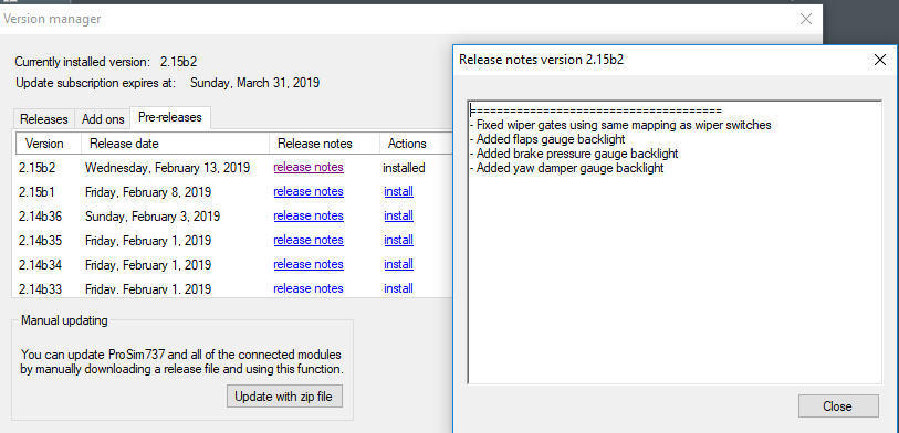
Included in the interface is a Version Manager that can be used to update the avionics suite.  When connected to the Internet, the Version Manager compares the release date of the currently installed avionics suite to the latest available release. 

The Version Manager enables the avionics suite to be updated from within ProSim737.  It's accessible from the User Interface (help/updates).

The Version Manager has three tabs:  Releases, Add-ons and Pre-releases.

Releases tab will display a list of final ProSim737 releases (along with release information and the date it was available).  To install the latest release, or to roll back to an earlier release, you select the install link in the Actions title.  This will cause the selected release to download and be installed to your computer copying over (and updating) a previous release installed.

Add-ons tab displays various add-ons that ProSim-AR have made available.  An example being the ProSim737 aircraft flight model.

Pre-release tab will display a list of beta releases.  Operation is identical to the releases tab discussed above.

One of the advantages of the Version Manager is that it enables you to quickly update the avionics suite to a beta pre-release, final release, or roll backwards to an earlier release.  It also provides information concerning the beta release (Release Notes tab), in addition to enabling you to monitor respective updates to the 737-flight model (Add-ons tab).

Three methods can be used to update the ProSim737 avionics suite:

(i)     Download the latest release from the ProSim-AR website (standalone requiring installation);

(ii)    Download the latest release from the Version Manager (zip file); or

(iii)   Download and install from the Version Manager a beta pre-release or final release.

There is no preferred method, however, option (iii) is the easiest way.

Version 3.00 Improvements to the Version Manager

In Version 3.00 additional improvements have been made to the Version Manager to aid in troubleshooting and the backing up of important files.

Opening the main ProSim menu and selecting Options (located beneath Connected Hardware) will open a Configuration File Manager & Mapping page.  This page displays the hardware family, type and mapping and whether the hardware is in use or not by ProSim (denoted by the colour).

Highlighting an item (text will change to red) and clicking the mappings section will open an additional table that displays a description of each function and its output port number for that particular interface card.  If you click the mappings table number a page opens displaying what function that card is connected.

Finally, at the bottom of the table are two tabs that enable you to create or restore a backup of the config.xml file (discussed in detail later on). 

A backup of the file is saved to C:\Program Data\ProSim-AR\ProSimB738\Backup\.  The config.xml backup is date named enabling consecutive backups of this file to be made and saved.

Beta Pre-release or Final Release ?

ProSim-AR regularly adds functionality and improvements to their avionics suite via beta pre-releases.  A beta pre-release enables users to test their hardware set-up with a release prior to it being finalised.  As such, beta pre-releases often have bugs, shortfalls and other problems associated with them. 

ProSim-AR have a dedicated web-based forum, and request that beta users provide feedback on a pre-release.  This enables issues to be rectified prior to making available a final release via the Version Manager.

The Updating Process

The ProSim737 Version Manager (if used) is smart enough to replace all files within the ProSim737 folder system, with the exception of configuration files and any file ending in .xml (these files are kept intact). 

However, if a release is downloaded from the ProSim-AR website, or the ZIP file option is used, then it will be necessary to manually insert the configuration files to their respective folders.  

ProSim737 updates in sequence.  This means, that after the software has been downloaded, the main ProSim737 module will be installed and run  first.  Then as each .exe file for each additional module is run, that module will update. 

A pop-up box will display 'updating configuration' as each module updates its content and synchronises with the main ProSim737 folder.  When an update to a module has been completed, the software will generate the updatelog.txt file (as discussed earlier). 

The time taken to update across a network between server and client computers depends upon your network speed; usually less than 30 seconds.  

Although theoretically not required, the Scenery Database (config/database) should be checked to ensure it's path is connected to the correct folder in Flight Simulator.  It also doesn't hurt to rebuild the database.  Rebuilding the Database following an update ensures that the link between the database, ProSim737 and Flight Simulator has not been corrupted.

Important Point:

  • Configuration files are generated in each folder as the .exe for each module is opened (run).

Customising How ProSim737 Updates

There are three ways that the User Interface can be set-up to update the avionics suite:

(i)     Manual updating;

(ii)    Ask before updating; and,

(iii)   Automatic updating.

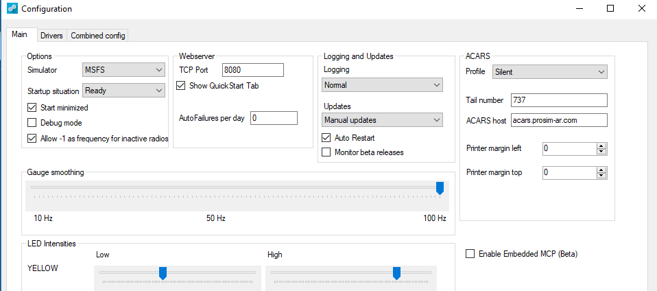
The method is customised in the User Interface, accessible from the drop down box (config/configuration/updates).  The interface also has a box that an be checked/ticked if you want the interface to monitor when a beta release becomes available; a screen pop-up will be displayed when you open the avionics suite.

Backups and Install from Backup

I recommend keeping a complete copy of each ProSim737 folder from the server and client computer.  By backing up the complete folder, you are also backing up the configuration and other important .xml files.

Theoretically, the Version Manager negates the necessity to maintain a backup of ProSim737 (or the configuration file), as the configuration and other .xml files are maintained intact.  However, by keeping a complete copy of the last ‘working’ release, it’s easy to ‘change out’ between releases (roll back or forward).  

All you need to do is delete the ProSim737 folders from the computer, and then copy/paste the earlier folders to the same locations.  All the files are intact and ProSim737 will load whatever release has been installed.

If you don't want to keep a complete copy of the folders and files, then it's also straightforward to roll back to an earlier release by using the Version Manager. The manager will download the selected release from the ProSim-AR server and install it overwriting the newer release on the computer.

My preference is to keep a complete copy the release and copy/paste if you want to roll back.

Automatic Backup of Config.xml File

The Version Manager has a handy tool automated within the software. It will now examine and compare the config.xml file during the updating process.  If the file is different between the two copies, the Version Manager will create a back-up copy called config-old.xml.

The auto backup provides a second level of protection to this important file.

Version 3.00 introduced the ability to easily backup and restore the config file.  Open the User Interface and select the small arrow (adjacent to options).  This will open a second window that examines what interface cards and hardware ProSim is connected with.  At the bottom of the page there is a command that enables you to save the config file or restore a backed up config file.  The file is saved within the ProSim file structure or you can select a preferred folder.

Important Points:

  • Always make a backup up your configuration (config.xml) files.  The config.xml file is the most important file in ProSim as it records your configuration and various user selected settings.

  • If downloading and installing a fresh copy of a release from the ProSim-AR website, then the configuration files will need to be manually added to each folder (from your backed up files).

  • Updates using the Version Manager replace all files within the ProSim737 folder system, with the exception of configuration files and any file ending in .xml.

  • The Version Manager displays the current release of ProSim737 you have installed.

  • A good idea to backup a copy of all the ProSim737 folders on both server and client computers.  Doing so allows you the option to easily replace a ProSim737 release with an earlier release number.

  • After running any update, the ProSim737 Scenery Database should be rebuilt.

Troubleshooting Updates

This section is not the ‘Holy Grail’ to resolve all problems.  Rather, it’s what should be done prior to requesting help from the ProSim-AR Development Group.  Some of the methods used to troubleshoot are quite simple, yet effective.

Occasionally there may be a problem with an update.  The update may cause one of the module’s .exe files to loop continually (open/close/open/close), or there may be limited functionality, or perhaps the ProSim737 main module will continually crash.

Recommended Initial Troubleshooting Protocols

Before spending valuable time in advanced troubleshooting, I suggest you check/do the following:

(i)     Shutdown all computers and restart;

(ii)    Ensure that all modules within all folders on the server and client computers have been updated to the new release (check the update file in the folder or check the release version number by right clicking the screen display and selecting configuration);

(iii)    Close and open all ProSim737 modules on the server and client computers;

(iv)   Check to ensure that the correct IP address is recorded for each display window opened.  To check this, right click the opened screen and select configuration.  This will open the screen’s user interface.  Check that the correct IP address recorded in the server box;

(v)    Check the version of .Net Framework on your client and server computer (discussed later);

(vii)  Replace the configuration file (config.xml) in the main ProSim737 folder with a copy of your backup configuration file;

(viii)  Delete all ProSim737 folders from your server and client computers and download/install from the ProSim-AR website a fresh copy of ProSim737 (remember to replace the configuration files in the ProSim737 folders to maintain your functionality settings and screen position); and,

(ix)     Open the User Interface (config/configuration) and confirm that the correct simulator (ie: FSUPIC, Sim Connect, MSFS) is listed in the options box.  Also ensure the enable embedded MCP beta is not selected, all installed  I/O modules and software are operational, and the simulator is connected.  Furthermore, check that all appropriate drivers have been selected for the add-on components and software you are using (config/configuration/drivers).

Usually problems are resolved by restarting your computer, reinstalling the config.xml file, or reinstalling ProSim737 from a fresh download.  

On rare occasions, the configuration file in the main ProSim737 module may have become corrupted during the update process (jumbled and altered assignments).  If you suspect a problem with the config.xml file, copy/paste your backup configuration file to the main folder.

Often, the easiest and fastest method to alleviate issues and save considerable time is to DELETE all instances of ProSim737 from the server and client computers and reinstall.  Before doing this make sure you have a backup of any files you may wish to keep (configuration files, etc.). 

Download the latest release of ProSim737 from the ProSim-AR website.  Copy the folders to the same location and add a copy of the respective configuration file to each folder.  Then, download the beta release (if required).

A quick word when trying to detect where a problem may be occurring.  Always test with a minimal or vanilla setup.  By this I mean deactivate on-line weather and winds and do not connect any add-ons other than those installed into the flight simulator platform (P3d, etc).  Test with a minimal setup; if everything is OK, then add the next program and so forth.

Advanced Troubleshooting, Log Files and the Input Debugger

If the above-mentioned ideas have failed, or the problem relates to a switch, toggle or USB disconnection of hardware, then the next option is to use some of the features available in the User Interface.  Namely the: System tabs, Driver tab, Input Debugger, Logging features, and Debug Mode. (config/configuration/main tab/drivers tab).  Let's look at each in turn.

Main Tab

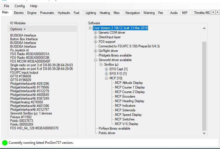
After opening the User Interface, the first tab that is usually seen is the Main tab.  The Main tab displays a list of registered and connected interface cards.  It also displays the add-on software components that are specific to your simulator configuration.  This screen is ‘live’ meaning that as you add or remove a device or interface card from the computer the connection (and list) will be updated.

The main tab is particularly helpful in identifying hardware USB disconnects (Windows USB disconnect ding-dong sound). 

In the case of USB disconnects, note any interface cards that you have connected that are either not displayed in the list, or flash on and off simultaneously with the ‘ding-dong’ sound; this will most likely be the offending card/device.  Often removing and replacing the USB connection will resolve a problem.

If the problem is a connection or functionality problem that relates to an add-on component (for example SimWorld MCP, CP Flight, Flight Deck Solutions, etc.).  Click the + symbol adjacent to the name of the device in the software list. This will expand the selected folder for the item in question.  Components not operating correctly, or not connected will be highlighted in red.

Enlarging on the above.   if you select option under I/O modules (located in the main menu) you are presented with 'storecurrentlistasrequired'.   This is a very handy feature in that it saves, as a profile, the interface cards used. If at anytime the cards connected to ProSim737 do not match this list, the disconnected card/harware will be displayed in red.

Important Point:

  • The list displayed in the Main tab includes all legacy components (for example, interface cards that previously may have been used but are now not connected).  To reflect the most up-to-date items, the configuration file in main ProSim737 folder must be edited.  This post in the ProSim-AR forum explains how to remove these entries: Removing Old Entries in Config File.

Drivers Tab

One of the advantages in using ProSim-AR, is that the developer has pre-installed and checked the connectivity of drivers for several add-on hardware components.  This removes the need to regularly update drivers.

The Drivers tab displays a list of all drivers that can be used with ProSim737.  For an add-on component to function, the driver specific to that component must be selected (checked/ticked/turned on).  If it isn't then the component will fail. 

If you have updated ProSim737 to a newer release, and have not used the Version Manager (manual update from the website), then there is a possibility that the correct drivers for your components have not been selected.

Functionality - Checking Inputs and Outputs (System Tabs and Input Debugger)

There are two ways that the User Interface can be used to check whether the movement of a component (input/output) is being registered by ProSim737 and operating correctly:  the System tabs and the Input Debugger.

System Tabs

The System tabs correlate to various aircraft and simulator systems, and when opened will display a list detailing the functionality of that particular system.

If the switch, toggle or whatever component in question is manipulated, there will be a corresponding indication shown in the Systems tab for that component.

I'm unsure if the System tabs were designed with problem troubleshooting in mind. Nevertheless, the various tabs can provide useful and helpful information and should form part of your troubleshooting system. 

Input Debugger

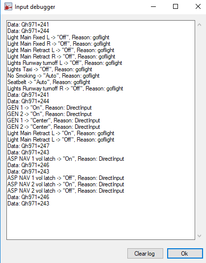
The Input Debugger (help/input debugger) is very easy to use, and the information it generates in its text box may help determine where a problem may reside.

The first time the Input Debugger is selected, a display window (debugger window) will open showing dozens of entries; the list can be confusing to read.  It's recommended to clear the list to make the debugger easier to use (press the clear list tab). 

With the Input Debugger open, you physically move the component in question (switch, toggle, lever, etc).  As soon as you move the component, you will note that its input, output and other related information is displayed in the debugger window.

The use of the Systems tab and Input Debugger is an ideal way to check that ProSim737 has registered the movement (input/output) of a component.

There is also a MCP debug option located in the config file of the MCP module (Version 2.30).  Opening the debug option in the MCP only displays information concerning the MCP.

Debug Mode

The debug mode is an advanced option that should only be used when requested by the Development Group (config/configuration/main/debug mode).   Some explanation of the mode is needed.

ProSim737 will only generate a crashlog.txt that relates to problems within its own software; it will not generate a crashlog.txt file if the problem is located outside of its software.  In such circumstances, the debug mode can be used to force ProSim737 to generate a crashlog.txt file.  This may aid in troubleshooting.

The debug mode will generate a large volume of entries, which to anyone but a software developer will be  nonsensical.  The generated files should be sent to the Development Group.

A further debug mode is located in the MCP tab (config/configuration/main/MCP).  As the name suggests this debugging tool should only be used when there are problems occurring with the MCP.

Important Points:

  • If the problem you are experiencing does NOT generating a crashlog.txt file (after deleting the file), then the problem is NOT related to the ProSim737 software, but rather to an outside source.

  • The debug mode should ONLY be used to generate the crashlog.txt file, after which it should be turned off.  Furthermore, it should only be used if requested by the Development Group.

Log Files

ProSim737 generates a number of log and crashlog files that can be examined to determine problems.

The two primary files, which are located in the main ProSim module folder are the log-System.txt and crashlog.txt files.

Further log files (log-Display.txt, crashlog,txt, log-Audio.txt, etc) can be found in the various ProSim modules (for example, display folders, CDU folder and audio folder).  Secondary log files can also be generated for LNAV and VNAV using HTP protocols.   Scrutinizing these files can often provide incite to the cause of a problem.

The log files, with time can become quite voluminous.  This is because additional information is added to the log every time ProSim737 is opened.  Often it’s easier to view a file that displays information that relates to the last simulation session. Therefore, when trying to troubleshoot an issue, it's a good idea to delete the log-System.txt and crashlog.txt files; the software will automatically generate both files from scratch when ProSim737 is re-run, and the resultant entries will only record the data from the last simulator session - this makes for easier reading.

Sometimes more detail is required in a log file.  To select more detailed (aka verbose) logging, open the User Interface (config/configuration/main/logging).  In the Main tab, beneath Logging and Updates, there is a drop down box - select either normal or verbose logging. 

It’s recommended, when using the simulator, to leave logging set to normal (unless testing).  The reason for this is because the verbose option will generate a significant increase in the number of entries to the various logs with a subsequent increase in system resources.  

If a crash log file is not generated for some reason, navigate to the Windows Event Viewer.  The Event Viewer may provide further information (Google Event Viewer if you are unsure what this is).

In addition to the primary log files, secondary log files can be used to harvest information pertinent to a specific system; for example, VNAV and LNAV.  These files should only be enlisted when requested from the Development Group. 

LNAV log files can be viewed by opening your web browser and selecting 127.0.0.1:8080/lnav or vnav (you replace the address with your own address).

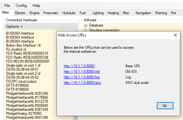
An additional log, that more or less duplicates the information found in the system-log.txt file can be viewed by accessing the web-based URL (help/web access URL's) - http//10.1.1.6 8080/log.  A shortcut to this can be found under the help tab in the ProSim User Interface window.  Web-based URL's were used in earlier versions of ProSim

Important Points:

  • ProSim737 will generate a new log-System.txt and crashlog.txt file if either of the files are deleted. 

  • Whenever posting to the ProSim-AR forum a question concerning a problem, its a very good idea to attach the log-System.txt and crashlog.txt files to the thread.  These files can then be perused by the Development Group.

Other Potential Causes of Problems

The list could be infinite!  However, the following 'potential culprits' seem to regularly cause problems for some users.

Opening Sequence of ProSim737 Modules and Flight Simulator

Sometimes following an update, ProSim737 will crash (drop-out).  If this should occur, there may be an issue with the sequence that the various programs are opened (run).

Theoretically, all the ProSim737 modules should connect automatically with the main ProSim737 module no matter what sequence they are opened. This said, changing the sequence that the ProSim737 main module is opened can resolve the issue.

Some users have reported that opening P3d/FSX before ProSim737 resolves drop-out issues, while others indicate the opposite.  Likewise, some users report that the main ProSim737 module should be opened prior to opening the other ProSim737 modules.

Whatever the sequence, changing the sequence that programs are opened should form part of your initial troubleshooting regime.

Important Point:

  • Always start of the ProSim737 System module using 'Administrator Rights'.

Windows Power Management Settings

If a USB device disconnect occurs after a period of elapsed time, then the computer’s Power Management Settings should be checked.

The Power Management Settings  enable the computer to turn off a device to save power; this is done following a period of elapsed time, or after a device has not been used for some time (for example, USB devices and display monitors).

Earlier operating systems maintained the settings established in Power Management, however, Windows 10 has a nasty habit of changing the Power Management settings without warning.  Therefore, the first check should be the device manager to check that the settings are as they should be.  

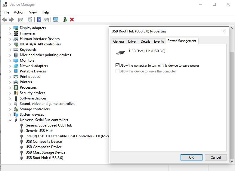
In the Device Manager dialog box, expand the Universal Serial Bus controllers tab, right-click each USB Root Hub, and click Properties. In the USB Root Hub Properties dialog box, click the Power Management tab.  The setting that allows the computer to turn off the device must be turned OFF (do not tick/check).

Additionally, check the Power and Sleep options. Depending on the operating system used, there may also be other tabs associated with power options.  Search Advanced Power Settings/USB/ and suspend/disable power management or sleep function.

USB Disconnects and Other Hardware Issues

The list is almost infinite.  However, for those using a number of interface cards and relays, a potential problem can be located with the USB cable, cleanliness and tightness of USB connections (including any USB hub), and loose wiring (especially if connectors have been used).

Clean the USB connections with a quality cleaner to ensure cleanliness and make sure the USB connectors are tight.  If the connectors need tightening, this can easily be done by pushing the small tabs inward on the female USB connection.

Surprisingly, wires that have been connected to relays by connectors can also work their way loose either from the connector blade on the relay or from the connector themselves.  This is caused by the continually opening and closing of the connected relays (movement and vibration), and by the continual heating and cooling of the wires (which can loosen wires from the connector).

Terrain Database (DEM) Installation

The Terrain Database is a separate folder downloaded from the ProSim-AR website.  The data when downloaded is in a zip file which when uncompressed should install the terrain data to a folder called DEM located at:  C:/Program Data/ProSim-AR/

Sometimes the installer doesn't function correctly.  If this happens, uncompress the files to your computer's desktop (or wherever) and copy the folder called DEM (and its files) to the location above.  When done correctly you should have folder called DEM in C:/Program Data/Prosim-AR/DEM

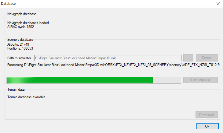
Once the files are installed, run the ProSim737 main module (.exe file) and enter the menu at the top of the User Interface.  Select CONFIG and rebuild the database.  The User Interface should have displayed 'Terrain Database Available'.

The information from the terrain database is recorded in the logdbbuild.txt file located in the main ProSim module folder.

Navigraph Data Installation

Navigraph is the navigation database used by ProSim737.  It is a purchased separately to ProSim. 

The correct navigation database (at time of writing) to download from the Navigraph website is ProSim737 2.24b1 (and above).

Navigraph have an installer (FMS Data Manager) which a standalone program that is free to use.  When setup correctly, the installer will download, uncompress, and install the Navigraph files to the correct folder structure on yuor computer.

Once the database is installed or updated, the ProSim737 main module (.exe file) must be run, and the database rebuilt (User Interface - select CONFIG and rebuild the database).   The database AIRAC cycle number will be displayed in the User Interface.

If the database does not update, there is a possibility that either that downloaded file is corrupt, or more than likely the database has been installed to the incorrect folder structure.

In this case, uncompress the downloaded files to your computer desktop (or anywhere) and copy the database to C:/Program Data/Prosim-AR/Navdata.  

Important Point:

  • Whenever you install the Navigraph database, rebuild the database and check the AIRAC cycle.

.Net Framework

Without going into detail, .Net Framework (pronounced Dot Net) is a language that is designed to bridge other computer languages so that they can be understood.  .Net Framework is designed and written by Micro$oft, and ProSim-AR have used it in newer releases of ProSim737.  

.Net Framework must be installed to all client and server computers.

Windows 10 Updates

Windows 10 has a feature that automatically updates essential files (as determined by Micro$oft) when the computer is connected to the Internet.  Often, the user is unaware that the files have been updated, as the update occurs in the background.

Sometimes a problem will occur when a Windows update deselects features in ProSim737 that are required.  For example drivers.

The Windows 10 updating feature can be deactivated if you use Windows 10 Professional, however, it cannot be deactivated in the Home edition (without registry hacking and other work-arounds). 

Batch Files and Shortcuts

It’s common for individuals to use a batch file to open ProSim737, or at the very least to use a shortcut to the original .exe file within a specific folder.  It’s also commonplace to rename the .exe file to something meaningful other than ProSim Display (of which there are several instances).  

DO NOT rename the original .exe file.  Rather make a shortcut to the file (right click and make shortcut) and rename this file.  If you do rename the original .exe file, the Version Manager will not replace the renamed .exe file and the release update will fail.

Hardware/Mapping

The config.xml file contains the information needed for ProSim to connect with whatever hardware you are using.  Often this hardware changes as items become obsolete and are replaced - for example, interface cards may be updated.  The Hardware/Mappings section of the config file will not these changes.  Rather, it will add new hardware mappings to the list.

To clean up the mappings section, it is necessary to open the config.xml file in a text editor and delete all entries between the <Hardware> section headers.  When the ProSim main menu is opened, a new hardware/mappings section will be generated that includes only the current hardware connected.

ProSim737 Flight Model

ProSim737 has a dedicated flight model for P3D and MSFS-2020.

The flight model has a built in installer which makes the process of installing straightforward - providing you follow the instructions as written by the developer in the opening screen.  The flight model is installed to the main P3D folder or to the community folder if using MSFS-2020.  If using the later, the flight model can be installed to a generic folder outside of the community folder and then linked to the community folder.

Prior to installing a new flight model, it is recommended to uninstall the earlier flight model.  This can be done by using the add/remove program options in Windows or by opening the uninstaller program that comes with the flight model.  Whichever option is selected, you must understand that the installation of the newer flight model will replace any existing files that relate to the model.

The files that are affected are those that reside in the aircraft folder.  The below folder is the location of the folder in my computer running MSFS-2020.  Your location will be different, however, the bolded entry is generic for all users.

D:\\Flight Simulator\MSFS2020Community Folder\Aircraft\prosim-B738-v2023\SimObjects\Airplanes\prosim-b738-2023.

Installation of a new flight model will replace any altered files, additional sound files, and added aircraft liveries with default files.  I strongly recommend that you backup the aircraft folder prior to updating the flight model.  After the new flight model is installed, you can then change-out any files that you want from the previous model.

Important Point:

Always backup the aircraft folder.  Uninstalling or installing a new flight model will delete and replace any files within the aircraft folder with default files.

Dedicated Forum and Requesting Help

ProSim-AR has a dedicated forum that is actively monitored by the Development Group. 

If unable to resolve your issue, the log.txt and crashlog.txt files can be posted to the forum along with a detailed subject line and description of the problem.  In most cases, the Development Group rectify problems quickly.  Failing this, you can submit a support ticket via the ProSim-AR website.

Important Points:

  • I cannot emphasis the importance of a detailed subject line.  It's counter intuitive to think that someone will open a thread that says "Help Me" or "Problem PS Doesn't Work" as opposed to "Marker Sound Not Working With PS Audio", or "MCP Disconnects when Opening ProSim".

  • When your issue has been resolved, open the thread and write RESOLVED in the title line.  This will stop forum members from opening your post to offer help, when in fact the problem is solved.

Disclaimer

The above mentioned information is valid as at the time of writing with Release Version 2.28b3.  However, ProSim-AR frequently update their software, and a future update may change what I have documented.

Final Call

The procedure to update the ProSim737 avionics suite is relatively straightforward, and the updating process streamlined and effective.   Nevertheless, the avionics suite is a complex piece of software and problems can occur following an update.  

The User Interface and Version Manager are powerful tools that can be used to customize the way that ProSim737 is updated and configured, and be used to troubleshoot problems.  Additionally, highly detailed logs can be generated which can be used by the Development Group to aid in rectifying problems.  This said, often the easiest solution to resolve a problem is to reinstall ProSim737 to its virgin state (from the ProSim-AR website), and reinstall your backed up configuration files.

This article has dealt primarily with updating and some of the potential problems that may develop; troubleshooting has only been briefly addressed.  Despite this, the above-mentioned recommendations should rectify most of the problems that may present when updating the avionics suite.

Acronyms and Glossary

  • Development Group - ProSim737 Development Group (software developer).

  • Level D/Type 7 Simulation - Full flight simulator (FFS) is a term used by national (civil) aviation authorities (NAA) for a high technical level of flight simulator. ... A Level D/Type 7 simulator simulates all aircraft systems that are accessible from the flight deck and are critical to training.

  • Manipulate - A term to mean move.  It could be a switch, toggle, button, lever or anything else that can be physically moved.

  • Run - Term meaning to run or open a program.

  • User Interface - The User Interface used to access the customizable features of ProSim737.  The User Interface is accessible by clicking the ProSim737 icon.

  • Version Manager – ProSim737 user interface used to configure and customise the ProSim737 avionics suite.

Update

  • Updated 11 April 2020

  • Updated 19 March 2023 (amended to include important changes made to the Version Manager in Version 3)

Wind Correction (WIND CORR) Function - CDU

OEM 737 CDU showing WIND CORR display in Approach Ref page

Wind Correction (WIND CORR)

The approach page in the CDU has a field named WIND CORR (Wind Correction Field or WCF). 

WIND CORR can be used by a flight crew to alter the Vref + speed (speed additive) that is used by the autothrottle during the final approach.   This is to take into account wind gusts and headwind that is greater than 5 knots. 

Changing the Wind Correction to match increased headwind and gusts increases the safety margin that the autothrottle operates, and ensures that the autothrottle command a speed is not at Vref.

WIND CORR Explained

The algorithm of the autothottle includes a component that includes a speed additive.  The speed additive is 1.23 times greater than the stall speed of the aircraft (at whatever flap setting).  When the autothrottle is engaged, the speed additive is automatically added to Vref.   This provides a safety buffer to ensure that the autothrottle does not command a speed equal to or lower than Vref. This added speed is usually 'bled off' during the flare ensuring landing is at Vref.

Although the autothrottle algorithm is a sophisticated piece of software, there is a time lag between when the sensors register a change in airspeed to when the physcial engines increase or decrease their spool (power).   By having a speed additive (based on headwind and gust component) the speed of the aircraft (as commanded by the autothrottle) should not fall below Vref.

A Vref+ speed higher than +5 can be inputted when gusty or headwind conditions are above what are considered normal.  By increasing the additive speed (+xx), the  speed commanded by the autothrottle will not degrade to a speed lower than that inputted.

The default display is +5 knots.   Changing this figure will alter how the algorithm calculates the command speed for the autothrottle; any change will be reflected in the LEGS page, however not in the APPROACH REF page.

The data entered into the Wind Correction field will only be used by the Flight Management System (FMS) when the aircraft is following an RNAV approach, or when using VNAV to fly an approach that has been manually constructed in the CDU.  This is because these approach modes use the data from the FMS to fly the approach (as opposed to an ILS or other mode that doesn't use the FMS data). 

If hand flying the aircraft, or executing another approach type, Wind Correction is advisory (you will need to add the speed additive (Vref+ xx knots) by mental mathematics).

Important Points:

  • Wind Correction is automatically added to Vref when flying an RNAV approach, or when using VNAV to fly an approach that has been manually constructed in the CDU.

  • Wind Correction is advisory for all other approach types or when manually flying an approach; +xx knots must be added to Vref by mental mathematics.

How To Use WIND CORR

The WIND CORR feature is straightforward to use.   

Virtual CDU (ProSim737) showing the difference in landing speed with a Vref between a +5 and +13 Knot (Wind Correction) change.  Vref altered from 152 knots to 160 knots

Navigate to the approach page in the CDU (press INIT REF key to open the Approach Reference page).  Then double press the key adjacent to the required flaps for approach (for example, flaps 30).  Double selecting the key causes the flap/speed setting to be automatically populated to the FLAP/SPD line. 

Type the desired additive into the scratch pad of the CDU and up-select to the WIND CORR line.  The revised speed will change the original Vref speed and take the headwind component into account.  If you navigate to the LEGS page in the CDU, you will observe the change.

If the headwind is greater than 5 knots, then WIND CORR can be used to increase the additive from the default +5 knots to anything up to but not exceeding 20 knots. 

It’s important to understand that the figure generated in the CDU is the Vref speed.  This is the speed that the aircraft should be at when crossing the runway threshold or at a altitude of approximately 50 feet.  

To this speed you must add the appropriate wind correction - either by mental mathematics or by using WIND CORR (if flying an FMS generated approach).

Boeing state that the +XX knots should be bled off during the flare procedure ensuring that touchdown speed is at Vref, however this rarely occurs in real life.

Recall from above, that any change using the Wind Correction field will have no bearing on calculations, unless the aircraft is being flown in RNAV / VNAV, or the approach has been manually constructed in the CDU.

For a full review on how to calculate wind speed, refer to this article: Crosswind landing Techniques - Calculations. A prompt sheet is displayed for quick reference.         

Wind calculation cheat sheet

Important Variables - Aircraft Weight and Fuel Burn

To obtain the most accurate Vref for landing, the weight of the aircraft must be known minus the fuel that has been consumed during the flight.

Fortunately, the Flight Management System updates this information in real-time and provides access to the information in the CDU.  It's important that if an approach is lengthy (time consuming) and/or involves holds, the Vref data displayed on the CDU will not be up-to-date (assuming you calculated this at time of descent); the FLAPS/Vref display will show a different speed to that displayed in the FLAP/SPD display.  To update this data, double press the key adjacent to the flaps/speed required and the information will update to the new speed.

How To Manually Calculate Fuel Burn

If wishing to manually calculate the final approach speed well before the approach commences, then it's necessary to manually calculate the fuel burn of the aircraft.  Open the PROGRESS PAGE on the CDU and take note of the arrival fuel.  Subtract this value from how much fuel you have in the tanks - this is the fuel burn (assuming all variables are constant).

Interestingly, the difference that fuel burn and aircraft weight can play in the final Vref speed can be substantial (assuming all variables, except fuel, are equal).  To demonstrate:

  • Aircraft weight at 74.5 tonnes with fuel tanks 100% full – flaps/Vref 30/158.

  • Aircraft weight at 60.0 tonnes with fuel tanks 25% full   – flaps/Vref 30/142.

Important Points:

  • During the approach, V speeds are important to maintain.  A commanded speed that is below optimal can be dangerous, especially if the crew needs to conduct a go-around, or if winds suddenly increase or decrease.  An increase or decrease in wind may cause pitch coupling.

  • If executing an RNAV Approach or using VNAV, it's important to update the WIND CORR field to the correct headwind speed based on wind conditions.  This is because an RNAV approach and VNAV use the data from the Flight Management System (to which Wind Correction is added).

  • If an approach is lengthy (for example, during a STAR or when requested to hold), the Vref speed will need to be updated to take into account the fuel that has been used by the aircraft during the holding time. 

  • Changing the WIND CORR speed in the CDU, does not alter the Vref speed displayed on the Primary Flight Display (PFD).  Nor is the APPROACH REF page on the CDU updated.  The change is only reflected in the LEGS page.

  • Boeing state that the speed additive should be 'bled off' during the flare so that the actual landing speed is Vref.

Autoland

Autolands are rarely done in the Boeing 737, however, if executing an autoland, the WIND CORR field is left as +5 knots (default).  The autoland and autothrottle logic will command the correct approach and landing speed.

Simulated in Avionics Suite

WIND CORR may or may not be functional in the avionics software you use.  Wind Correction is functional in the ProSim737 avionics suite.

Additonal Information

A very good video that discusses this in detail can be viewed at FlightDeck2Sim.


Acronyms

  • CDU – Control Display Unit

  • FMC – Flight Management Computer

  • FMS – Flight Management System (comprising the FMC and CDU)

  • Vref - The final approach speed is based on the reference landing speed

  • Vapp – Vapp is your approach speed, and is adjusted for any wind component you might have. You drop from Vapp to Vref usually by just going idle at a certain point in the flare

  • Updated 21 March 2022 (increased clarity)

How To Calibrate Flight Controls in Flight Simulator Using FSX, Prepar3D or FSUIPC

Imagine for a brief moment that you are driving an automobile with a wheel alignment problem; the vehicle will want to travel in the direction of the misalignment causing undue stress on the steering components, excessive tyre wear, and frustration to the driver. 

Similarly, if the main flight controls are not accurately calibrated; roll and pitch will not be correctly simulated causing flight directional problems, frustration and loss of enjoyment.

Flight controls are usually assigned and calibrated in a two-step process, first in Windows, then either by using the internal calibration provided in the FSX, Prepar3D, ProSim737, or using the functionality provided by FSUIPC.

It's often easier to think of calibrating controls as a two-stage process - Primary Calibration (in Windows) and Secondary Calibration (in Prosim737, flight simulator, or FSUIPC).

In this post, the method used to assign and calibrate the main flight controls (ailerons, elevators and rudder pedals) in FSX, Prepar3D and FSUIPC will be discussed.  Internal calibration in ProSim737 will not be discussed.  The common theme will be the calibration of the ailerons, although these methods can calibrate other controls. The calibration of the throttle unit will not be discussed.

Many readers have their controls tweaked to the tenth degree and are pleased with the results, however, there are 'newcomers' that lack this knowledge.  I hope this post will guide them in the 'right direction'.

STEP 1 - Calibrating and Registering Control Devices in Windows (Primary Calibration)

All flight controls use a joystick controller card or drivers to connect to the computer.   This card must be registered and correctly set-up within the Windows operating system before calibration can commence.  

  • Type ‘joy’ into the search bar of the computer to open the ‘game controllers set-up menu’ (set-up USB game controllers).  This menu will indicate the joystick controller cards that are attached to the computer (Figure 1). 

  • Scroll through the list of cards and select the correct card for the flight control device.  Another menu screen will open when the appropriate card is selected.  In this menu, you can visually observe the movements of the yoke, rudder pedals and any yoke buttons that are available for assignment and use.  The movement of the controls will be converted to either a X, Y or Z axis (Figure 1).

  • Follow the on-screen instructions, which usually request that you move the yoke in a circular motion, stopping at various intervals to depress any available button on the device.  The same process is completed for the movement of the control column (forward and aft) and the rudder pedals (left and right).  Once completed, click ‘save’ and the profile will be saved as an .ini file in Windows.


FIGURE 1:  Windows Joystick Calibration User Interface or Game Controller Interface in (Primary Calibration of joystick controllers)


Registration is a relatively straightforward process, and once completed does not have to be repeated, unless you either change or reinstall the operating system, or recover from a major computer crash, which may have corrupted or deleted the joystick controller’s .ini file. 

STEP 2 - Assigning Flight Control Functionality in FSX and Prepar3D (Secondary Calibration)

  • Open FSX or Prepar3D and select from the menu ‘Options/Settings/Controls’.  The calibration, button key and control axis tab will open (Figure 2).

  • Select the ‘Control Axis’ tab. When the tab opens, two display boxes are shown.  The upper box displays the joystick controller cards connected to the computer while the larger lower box displays the various functions that can be assigned.  The functions that need to be assigned are ailerons, elevators and rudders.

  • Select/highlight the appropriate entry (i.e. ailerons) from the list and click the ‘Change Assignment’ tab.  This will open the ‘change assignment’ tab (Figure 3).  Physically move the yoke left and right to its furthest extent of travel and the correct axis will be assigned.  To save the setting, click the ‘OK’ button. 

  • When you re-open the ‘Control Axis’ tab you will observe that the function now has an axis assigned and this axis is identical to the axis assigned by Windows when the device was registered.  You will also note a small box labelled ‘Reverse’.  This box should be checked (ticked) if and when the movement of the controls is opposite to what is desired (Figure 3). 

  • Save the set-up by clicking the ‘OK’ button.


FIGURE 2:  FSX Settings and Controls Tab (Prepar3D menus are similar)


FIGURE 3:  FSX Change Assignment Menu


STEP 3 - Calibrating Flight Controls in FSX and Prepar3D

The flight control functions that have been assigned must now be calibrated to ensure accurate movement.   

  • First, select and open the ‘Calibration’ tab.  Ensure the box labelled Enable Controllers(s)’ is checked (ticked) (Figure 4).

  • The correct joystick controller card must be selected from the list displayed in the box beside the controller type label.

Whether simple or advanced controls are selected is a personal preference.  If advanced controls are selected, the various axis assignments will be shown in the display box.  The axis, sensitivity and null zone can be easily adjusted using the mouse for each of the flight controls (ailerons, elevators and rudders). 

Concerning the sensitivity and null zone settings.  Greater sensitivity causes the controls to respond more aggressively with minimal physical movement, while lesser sensitivity requires more movement to illicit a response.  It is best to experiment and select the setting that meets your requirement.

The null zone creates an area of zero movement around the centre of the axis.  This means that if you create, for example, a small null zone on the ailerons function, then you can move the yoke left and right for a short distance without any movement being registered. 

Creating a null zone can be a good idea if, when the flight controls are released, their ability to self-center is not the best.  Again, it is best to experiment with the setting.  To save the settings click the ‘OK’ button.  


FIGURE 4:  FSX Settings and Controls


This completes the essential requirements to calibrate the flight controls; however, calibration directly within FSX or Prepar3D is rather rudimentary, and if greater finesse/detail is required then it's recommended to use FSUIPC.  

FSUIPC

FSUIPC pronounced 'FUKPIC' is an acronym for Flight Simulator Universal Inter-Process Communication, a fancy term for a software interface that allows communication to be made within flight simulator.  The program, developed by Peter Dowson, is quite complex and can be downloaded from the website.  FSUIPC allows many things to be accomplished in flight simulator; however, this discussion of FSUIPC, will relate only to the assigning and calibrating of the flight controls.

It's VERY important that if FSUIPC is used, the FSX or Prepar3D ‘Enable Controllers’ box must be unchecked (not ticked) and the joystick axis assignments, that are to be calibrated in FSX or Prepar3D be deleted.  Deleting the assignments in optional, however, recommended.  The flight controls will only function accurately with calibration from one source (FSX, Prepar3D or FSUIPC)

STEP 1 - Assigning Flight Controls Using FSUPIC

  • Open FSX or Prepar3D and from the upper menu on the main screen select Add Ons/FSUIPC’.  This will open the FSUIPC options and settings interface (Figure 5).

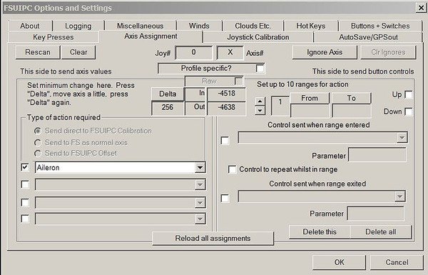
  • Navigate to the ‘Axis Assignment’ tab to open the menu to assign the flight controls to FSUIPC for direct calibration (Figure 6).

  • Move the flight controls to the full extent of their movement.  For example, turn the yoke left and right or push/pull the control column forward and aft to the end of their travel.  You will observe that FSUIPC registers the movement and shows this movement by a series of numbers that increase and decrease as you move the flight controls.  It will also allocate an axis letter.

  • At the left side of the menu (Figure 6) is a label ‘Type of Action Required’; ensure ‘Send Direct to FSUIPC Calibration’ is checked (ticked).  Open the display menu box directly beneath this and select/highlight the flight control functionality (ailerons, elevator or rudder pedals).  Check (tick) the box beside the function.


FIGURE 5:  FSUPIC Main Menu


FIGURE 6:  FSUIPC Axis Assignments


Calibrating Flight Controls Using FSUIPC

  • Select the Joystick Calibration’ tab.  This will open an 11 page menu in which you calibrate the flight controls in addition to other controls, such as multi-engine throttles, steering tiller, etc.  Select page 1/11 'main flight controls' (Figure 7)

  • Open the ‘Aileron, Elevator and Rudder Pedals’ tab (1 of 11 main flight controls).  Note beside the function name there are three boxes labelled ‘set’ that correspond to min, centre and max.  There is also a box labelled ‘rev’ (reverse) which can be checked (ticked) to reverse the directional movement of the axis should this be necessary.  The tab labelled ‘reset’ located immediately below the function name opens the calibration tool.  The ‘profile specific’ box is checked (ticked) when you want the calibration to only be for a specific aircraft; otherwise, the calibration will be for all aircraft (global).  The box labelled filter is used to remove spurious inputs if they are noted and for the most part should be left unchecked (not ticked).  The tab labelled ‘slope’ will be discussed shortly.

  • Click the ‘reset’ tab for the ailerons and open the calibration tool.  Move the yoke to the left hand down position to its furthest point of travel and click ‘set’ beneath max.  Release the yoke and allow it to center.  Next, move the yoke to the right hand down position to its furthest point of travel and click ‘set’ beneath min.  Release the yoke and allow it to center.  If a null zone is not required, click the ‘set’ beneath centre.

If a problem occurs during the calibration, the software will beep indicating the need to restart the calibration process.  The basic calibration of the yoke is now complete.  However, to achieve greater accuracy and finesse it is recommended to use null zones and slope functionality.


FIGURE 7:  FSUIPC Joystick Calibration (ailerons, elevator and rudder)


Null Zones

The null zone concept has been discussed earlier in this article.

If a null zone is required either side of the yoke center position, move the yoke to the left a short distance (1 cm works well) and click ‘set’ beneath centre.  Next, move the yoke 1 cm to the right and click ‘set’ beneath centre.  

As you move the yoke you will observe in the side box a series of numbers that increase and decrease; these numbers represent the movement of the potentiometer.  It is not important to understand the meaning of the numbers, or to match them.

Replicate the same procedure to calibrate the elevators and rudder pedals (and any other controller devices)

To save the setting to the FSUIPC.ini file click ‘OK’

It is a good idea to save the FSUIPC.ini file as if a problem occurs at a later date, the calibration file can easily be resurrected.  The FSUIPC.ini file is located in the modules folder that resides in the FSX or Prepar3D route folder.  

Slope Functionality

Slope functionality is identical to the sensitivity setting in FSX and Prepar3D.  Decreasing the slope (negative number) causes the controls to be more sensitive when moved, while a positive number reduces the sensitivity. To open the slope calibration, click the ‘slope’ tab.  This will open a display box with an angled line.  Manipulating the shape of this line will increase or decrease the sensitivity.

Slope functionality, like the null zone requires some experimentation to determine what setting is best.  Different flight controls have differing manufacturing variables, and manipulating the slope and null zone allows each unit to be finely tuned to specific user preferences.

Does FSUIPC make a Difference to the Accuracy of the Calibration ?

In a nutshell – yes.  Whilst the direct assignment and calibration in FSX and Prepar3D is good, it's only rudimentary.  FSUIPC enables the flight controls to be more finely adjusted equating to a more stable and predictable response to how the controls react.

Potential Problems

If using FSUIPC for axis assignment and calibration, remember to uncheck (not tick) the ‘enable controller’ box and delete the axis assignments in FSX or Prepar3D – only one program can calibrate and control the flight controls at any one time.  If calibration from both FSX or Prerpar3D and FSUIPC are used at the same time, spurious results will occur when the flight controls are used.

If the calibration accuracy of the flight controls is in doubt (spurious results), it is possible that the simulator software has inadvertently reassigned the axis assignments and enabled calibration.  

There's an intermittent issue in FSX and Prepar3D where the software occasionally enables the controllers and reassigns the axis assignment, despite these settings having been unchecked (not enabled).  If a problem presents itself, it's best to double check that this has not occurred.  This is why I recommend that the settings be deleted, rather than just being unchecked.

Final Call

Many enthusiasts are quick to blame the hardware, avionics suite, or aircraft package, when they find difficulty in being able to control the flight dynamics of their chosen aircraft.  More often than not, the problem has nothing to do with the software or hardware used, but more to do with the calibration of the hardware device.

The above steps demonstrate the basics of how to calibrate the flight controls - in particular the ailerons.  If care is taken and you are precise when it comes to fine-tuning the calibration, you maybe surprised that you are now able to control that 'unwanted pitch' during final approach.

Further Information and Reading

Documents relating to FSUIPC can be found in the modules folder in your root director of flight simulator on your computer.  The below link addresses how to calibrate the steering tiller.

List of B737 Carriers Worldwide - Interesting....

first boeing 727. lufthansa 1968 (Comet Photo AG (Zürich), ETH-BIB Com F66-08148 Lufthansa Boeing 727-3C D-ABIC Zuerich-Kloten 060766, CC BY-SA 4.0)

A Boeing 737 takes off or lands somewhere in the world on average every 5 seconds!

To date, the Boeing series of airliners is the most successful airliner the world has seen.  Boeing's success revolves around, amongst other things, the ability to be able to upgrade their aircraft from a basic overall design that has changed little since the first 727 rolled out of the hanger in the 1968, earmarked for the German airline Lufthansa.

So which nations place their trust in Boeing?  This link provides a list of worldwide carriers by nation.

Creating Waypoints on the Fly with the CDU

Often you need to inject into the flight plan a Place Bearing Waypoint or an Along Track Waypoint.  There are several ways to do this with each method being similar, but used in differing circumstances.  Depending upon the FMC software in use, either the LEGS or the FIX page is used.

A Place Bearing Waypoint (PBW) is a waypoint along a defined bearing (radial) that is created at a specified distance from a known waypoint or navigation aid (navaid).  A PBW is used to create  a waypoint that is not in the active route.

An Along Track Waypoint (ATW) is a waypoint inserted into a route that falls either before or after a known waypoint or navaid.

Although the PBW and ATW are similar, they are used in differing circumstances.

  • In the following examples I will use the waypoint TETRA as an example.  TETRA is a waypoint near Narita, Japan (RJAA).

Creating a Place Bearing Waypoint

  • Type into the scratchpad the waypoint name, bearing and distance.

    For example, type into the scratchpad a TETRA340/10.  TETRA is the waypoint that we want to create the new waypoint from.  This is called an anchor waypoint.  340 is the bearing in degrees from the anchor waypoint that the new waypoint will be generated.  10 is the distance in nautical miles from the anchor waypoint that the waypoint will be generated at.

  • Up-select TETRA340/10 to the LEGS page. 

  • Press EXECUTE.

To insert the waypoint before the anchor waypoint use the negative key (TETRA340/-10).  Do not use the negative symbol if you want to insert the waypoint after the anchor waypoint (TETRA340/10).  Take note that the slash (/) is after the bearing and the waypoint name and vector are joined with no spaces.

Creating an Along Track Waypoint

  1. Type into the scratchpad the waypoint or navaid that will be used as an anchor waypoint.

  2. Up-select this into the correct line of the route in the LEGS page.

  3. Press EXECUTE.

Important Points:

  • If the waypoint is already part of the route, it is not necessary to type the identifier in to the scratchpad.  Rather, press the appropriate Line Select Key adjacent to the identifier (in the LEGS page) to down select to the scratchpad.  Then add the /-10 or /20 after the identifier and up-select.  Using this method eliminates the possibility of typing the incorrect identifier into the scratchpad.

  • The FMC software will generate subsequent waypoints with a generic name and numerical sequence identifier.  For example, TETRA, TETRA01, TETRA02, TETRA03.

Creating a Circle around a Waypoint using the FIX Functionality

The purpose of creating a circle (ring) around a point in space is to increase spatial awareness when looking at the Navigation Display (ND).  A circle at a set distance may be used to define the Missed Approach Altitude (MAA), the distance from the runway threshold that the landing gear should be lowered, or to designate an important waypoint.

I nearly always use two or three circles depending upon the approach being executed.  One circle will be at 12 miles while the second circle will be at 7 miles.  The use of circles can be very helpful when flying a circle-to-land approach; one circle will define the MAA and the other circle will define the  'protected area' surrounding an airport.

To create a circle (ring) around a known point

  1. Press FIX on the CDU to open the FIX page.

  2. Type into the scratchpad, the name of the waypoint or navigation aid (VOR, NDB, etc).  For example TETRA.

  3. Up-select this to the FIX page (LSK1L).

This will display a small circle around the identifier in the Navigation Display in green-dashed lines.

If you want the circle to be at a specific distance from the point in question.

  1. Type into the scratchpad the distance you require the circle to be drawn around the waypoint.  For example /5.

  2. Up-select this to the FIX page (LSL2L).

To add additional circles around the selected point, repeat the process using different distances and up-select to the next line in the FIX page.

Important Point:

  • A quick way to insert a waypoint from a route into the FIX page is to press the waypoint name in the LEGS page.  This will down select the waypoint to the scratchpad saving you the time typing the name and removing the possibility of typing the incorrect letters.  Up-select to the FIX page.

Creating a Single Along Track Waypoint (at the edge of the circle)

One or more waypoints can be created anywhere along the circumference of the circle (discussed earlier) by inserting a bearing and distance into the FMC page.  

To create a waypoint at the edge of the circle

Create a circle around a point as discussed earlier (TETRA).

  1. Type in the scratchpad the bearing and distance that you wish the new waypoint to be created (for example 145/5).

  2. Up-select this information to the FIX page (LSK2L). This will place a green-coloured line on the 145 degree radial from the waypoint (TETRA) that intersects a circle at 5 miles on the ND.

  3. Next, select the 145/5 entry from the FIX page (press LSK2L).  This will copy the information to the scratchpad.  Note the custom-generated name – TETRA145/5.

  4. Open the LEGS page and up-select the copied information to the route.  Note that TETRA145/5 will now have an amended name – TET01.

  5. Copy TET01 to the scratchpad.

  6. Open a new FIX page (there are 6 FIX pages that can be used).  Up-select TET01 to the FIX page (LKL1L).  This will create a small circle around TET01 on the ND.

  7. To remove the waypoint (TET01) from the route (if desired), open the LEGS page and delete the entry.   If desired, the waypoint can easily be added again to the route from the FIX page.

The above appears very convoluted, however once practiced a few times it becomes straightforward.  There is a less convoluted way to do this, however, the method is not supported by ProSim737.

Inserting an Additional Along Track Waypoint around the Arc of the Circle (DME Arc)

A DME arc is a series of Along Track Waypoints that have been created along an arc at a set distance from the runway (waypoint or navigation fix).  This is often used when flying a NDB Approach.

Usually, the arc begins on the same bearing as the navigation track of the aircraft, and ends a set point, usually at the turn from base to final.  Subsequent bearings after the initial bearing are at a 30 degree spacing.

To create a DME Arc

First, ensure you have a circle created around the waypoint (TETRA) at the distance required (FIX page).

  1. Select the anchor waypoint (TETRA) for the arc from the LEGS page and down select it to the scratchpad.

  2. Type into scratchpad after TETRA (as separate entries) the bearing and distance.  For example: TETRA200/5, TETRA230/5, TETRA260/5, TETRA290/5 TETRA320/5 and so forth.  Note the bearings differ by 30 degrees.  This creates the arc.

  3. Up-select each of the above entries to the route in the LEGS page (after the anchor waypoint TETRA).

This will create an arc 5 miles from TETRA.

If you want the first waypoint to be along your navigation track, use the bearing for this initial waypoint as indicated in the LEGS page of the CDU.

The FIX page can also be used to create an arc using the same technique.  Using the FIX page will enable the arc to be seen on the ND, but not form part of the route.

Important Point:

  • It is important to note that user and along track waypoints are given a generic name and numerical sequence identifier by the FMC software (TETRA01, TETRA02. TETRA03, etc).

Understanding the CDU

What I have described above is but a very brief and basic overview of some functions that are easily performed by the CDU.

CDU operation can appear to be a complicated and convoluted procedure to the uninitiated.  However, with a little trail and error you will soon discover a multitude of uses.  It is important to remember, that there are often several ways to achieve the same outcome, and available procedures depend on which FMC software is in use.

I am not a professional writer, and documenting CDU procedures that is easily understood is challenging.  If this information interests you, I strongly recommend you purchase the FMC Guide written by Bill Bulfer.  Failing this, navigate to the video section of this website to view FMC tutorials.


Navigation display showing map view. Left to right.

image 1:  5 mile ring surrounding TETRA.

image 2: 2 and 5 mile ring surrounding TETRA.

image 3: 5 mile ring surrounding TETRA showing PBW on circumference TET01.

image 4: DME arc along circumference of 5 mile ring surrounding TETRA.


Acronyms

Anchor Waypoint – The waypoint from which additional waypoints are created from.

Bearing – Vector or radial.

CDU – Control Display Unit.

FMC – Flight Management Computer.

ND – Navigation Display.

Target Waypoint – The waypoint that has been generated as a sibling of the Anchor waypoint.

Waypoint – Navigation fix, usually an airport, VOR, NDB or similar.

  •  Updated 05 June 2022.

Construction Commenced - New Platform to Install OEM Control Columns

I thought it time to post what’s happening with regard to the construction of the simulator.  Additions and improvements are in the pipeline and it’s hoped that OEM control columns and a new platform will be installed very shortly.

Currently the simulator is mounted on a fiber-board and wood platform, which I constructed when I received my Main Instrument Panel (MIP) just before Christmas 2010.  The platform has served me very well and was perfect for the installation of the ACE yoke and Precision Flight Controls (PFC) rudder pedals.  

Soon after constructing the platform and purchasing the ACE yoke, I was able to secure two OEM B737-500 control columns. I was surprised to find these units so quickly and I was fortunate that my timing coincided with the dismantling of a late model B737-500.

Fitting the OEM control columns to the wooden platform appeared to be problematic, as the platform was a tad low in height and it was awkward to retrofit the linking rod that connects the control columns for duel operation.  Therefore, I decided that a new platform was required; custom designed  to fit the control columns.

Aluminium Modular Design

Rather than use wood and fiber-board, I selected aluminium tubing cut appropriately and TIG welded together.  To facilitate future transport, the platform has been constructed in modular form.  The forward portion comprises three modules bolted together in strategic places, while the rear part of the platform (not shown), where the seats and center pedestal reside, abuts snugly to the forward section.  It’s intended to use high density ¼ inch plastic/vinyl as the upper cover on the platform  as this material is easier to work than aluminium sheeting, is light in weight, very strong and comes from the factory in Boeing grey.

In the photographs (click to enlarge) you can see the control columns (striped completely) fitted to the forward modular section of the platform.  The control columns are connected to each other by a ¾ inch heavy duty shaft and heavy-duty double bearings.  Forward and aft movement of the control column is controlled by a heavy duty spring and left and right roll movement is controlled by another spring. 

Control Column Pull Pressures

The pull pressure on the control column is set to 24 pound which is slightly less that the standard pull in the B737 which is 34 pound.  The pull can be easily altered by moving the spring forward or backward on the spring retainer.  The pressure on the roll component is presently 12 pounds.  I've been told the roll pressure as per the Boeing maintenance manual is +_15 pound; therefore, I'm well within the ball park.

Telex Airman 750 Headset - Adding To Realism With Real Parts

oem telex 750 headset

To quieten some of the ambient sounds (dogs barking), I use a David Clark aviation headset (model H10 13-S) which is a left over from when I did my ]private pilots license (PPL).  This particular headset is a marvel of engineering and works exceptionally well for real world flying and simulator use.

Recently, I saw for sale in a wrecking yard, an airliner style Telex Airman 750 headset.  The price was $30.00 including freight from the USA to Australia.  To be honest, I wasn’t expecting too much – after all, what does one get for $30.00 these days!  I was pleasantly surprised when I opened the FEDEX sachet and an almost brand new headset, equipped with boom mike and tell-tail aviation style audio connectors and cable, fell onto the floor.  The foam ear pieces were still good condition, as was the small clip that attached the cable to your collar (to stop the cable from snagging).

After plugging in the headset to the Flight Sound X Adapter (click to see earlier review), I was even more surprised when the headset worked!  Sounds were crisp and easy to hear and the weight of the headset minimal.  The boom mike relayed my voice more than adequately across the network to VATSIM.

Using real aircraft parts adds to the realism of flight simulator; a headset being just one item.  I guess bargains still do exist.

Aircraft Liveries & Textures - Adding a Livery Texture To Your B738

For many flight simulator enthusiasts, there’s enjoyment knowing your flying the correct aircraft livery in the correct airspace.   For others, opening the exterior views to play back your landing sequence from the flight video just looks better with a nicely painted texture or livery.  FSX comes bundled with several B738 aircraft liveries, but most of us dislike them; it’s common for individuals to search forum sites such as AVSIM in an attempt to find a livery that suits their virtual airline.

Recently, I found a FS add on that includes 164 liveries of the B738 aircraft suitable for FSX.  The file, which includes an automatic executable, can be downloaded from the French flight sim website http://www.rikoooo.com/en/downloads/viewcategory/55.   The program will download to your simobjects/aircraft folder a folder named 164 aircraft.  Within this folder can be found all the textures and a correctly constructed aircraft .cfg file.  The program also includes a correctly configured airlines file which will over right your existing airline file with all the correct ATC calls for the various liveries.  This is a wonderful time saver for those who use ATC.  Access to the aircraft is as you would usually load an aircraft, airport and weather situation..  Note that you will be required to register to the forum site before you can download the program.

Below is a list of livery textures included in the package

Adam Air, Aeromexico, Aerosvit, Air Asia Indonesia, Air Astana, Air Berlin, Air Canada, Air China, Air China Olympic, Air Europa, Air France, Air Jamaica, Air New Zealand, Air One, Air Slovakia, AirTran Airways, Air Vanuatu, Alaska , Alaska.com, Alaska Spirit of Seattle, Alaska Starliner 75, Alitalia, All Nippon Airways (ANA), ALOHA, American Airlines, America West, Ansett Australia, Austrian Airlines, Batavia Air (x3), Bmibaby, British Airways, Brussels Airlines, Bulgaria Air, Caribbean Airlines, Cebu Pacific Air, Continental Airlines, Copa Airlines, Corendon Airlines, Cubana De Aviación, Cyprus Airways, Czech Airlines, Delta Airlines, DHL Cargo, EasyJet, Eastern AIrlines, El Al (Israel), EgyptAir, Europe Airpost, FedEx Cargo, Ferrari, Ferrari Cargo, Finnair, First Choice, Flash Airlines, Fly Dubai, Flyglobespan, Frontier Airlines, Garuda Indonesia, Garuda SkyTeam, GOL, Gulf Air, Hainan Airlines (x2), IRONMAIDEN, Japan Airlines (JAL), JAT Airways (old and new), Jet2 (grey and white), JetAmerica, JetTime,Kenya Airways, Landmark (Coliseum tail), Lion Air (Indonesia), LOT (Polish Airlines), Lufthansa, Luxair, Malaysia Airlines, MALEV, Mexicana (x4), Military Woodland Camo, Mongolian Airlines (MIAT), Montenegro Airlines, Myanmar Airlines (MAI) , NASA, NAVY, Norwegian Air, Northwest (NWA), OceanAir (Avianca), Olympic Airlines,  Pan-Am, Philippine Airlines, PIA (Pakistan Intenrational Airlines), Prague (Czech Republic), Primera Air JetX (Iceland), PrivatAir, Qantas, Ryanair, Ryanair Guinness, Ryanair Kilkenny, Ryanair Vodafone, Scandinavian Airlines (SAS), Singapore Airlines, South African Airways, Southwest Airlines (Blue, Gold, New Mexico), Sterling (Australia), SunExpress, Swiss Air, TAM (Brasil), TAROM (Romania), Thomson Airways, Transavia, TUIfly (x7), Turkish Airlines, Ukraine International Airlines (UIA), UNITED (old and new), UPS Cargo, US Airways, Varig (old and new), VASP (Brazil) , V Australia, Vietnam Airlines, Virgin (blue and red), WestJet, XL Airways, XL Airways Excel.com, XL Airways Öger Tours and XL Airways Viking.

I think you will agree, that anyone should be able to find something they like from this list.

Installing to the ProSim 737 JetStream

To use the textures in the ProSim737 Jetstream B738 aircraft, it will be necessary to edit the aircraft.cfg file.  I’ve outlined the process below.  Before proceeding, make a backup of the JetStream folder BEFORE making changes.  It’s always good policy to do this just in case a problem is experienced.

A:  Copy all the aircraft texture folders (located in the 164 folder), or the ones you want as 164 edits can take a long time...., to your Jetstream folder located in simobjects/aircraft.

B:  Open two windows, one with the aircraft .cfg file opened from the 164 aircraft folder and one with aircraft .cfg file opened from the Jetstream folder. 

C:  Open/click the Jetstream aircraft .cfg file for editing. There are four main edits that need to be made.

  1. The FLTSIM number needs to be edited to reflect the correct order within the file.  Check and make sure the first airline entry is 1 followed by 2, 3, 4, 5, 6, 7 and so forth.

  2. The TITLE must be title=Jetstream738 B737-800 Air New Zealand (or whatever livery)

  3. The Sim must be sim=Jetstream738

  4. The UI manufacturer must be ui_manufacturer=”A Jetstream-Boeing”

Duplicate the text from the above mention 4 lines from the 164 aircraft.cfg, for the aircraft liveries you want, to the Jetstream aircraft.cfg file.  it's important to do these edits as you want to link the livery texture to the Jetstream flight model.  The image shows a screenshot of one of the aircraft textures from my JetStream aircraft.cfg file.

I’ve bolded and coloured red the entries that need to be edited to reflect the new aircraft textures.  You may also wish to change the ATC flight number, but this isn’t necessary for correct operation.

You have probably observed that my naming structure is a little different to the norm.  The reason I begin the name with the letter A, is so that when I open the select aircraft tab in FSX, I don’t have to scroll down to J for JetStream.  Instead, the correct folder is located at the top of the list (The letter A is at the beginning of the English alphabet).

There you have it.  The methodology explained here can be used to add textures for any aircraft livery.   

Using PMDG 737-800 NGX Sound In The Default 737-800

I have received a few e-mails from individuals asking how to replace the default sound with the sound from the PMDG 737-800 NGX.  This is a relatively easy task and the improvement in audio quality and experience over the default B737 sound is second to none. 

Before continuing, I should state that PMDG have designed their NGX audio package to only be used with the PMDG flight model.  As such sounds that PMDG have mapped to specific actions within their flight model will not work outside the PMDG flight model.  I'm sure there is a way to strip the actual "specialist" sounds, but the time required outstrips the enjoyment.  This said, the basic engine sounds and environmental sounds are easily separated for use in other flight models, such as the default 737 and ProSim JetStream738 flight model.

In the examples below, my main FSX folder is located in a directory on C:/ drive and is named FS10.  You may have a different directory location and name for FSX.

Let's Begin....

When you install the PMDG 737NGX, the program copies audio to the following folders:

  1. FS10/simobjects/airplanes/PMDG 800 NGX/sound    (main engine sounds & some environmental sounds)

  2. FS10/sound/PMDG 737-800NGX/sound......   (specialist sounds such as gear lever movements, switches, call outs, etc)

The default B737-800 model’s audio is located in the default 737/800 folder (FS10/simobjects/aircraft/737-800/sound)

Make a copy of the sound folder and store to desktop in case of an issue.  Then, delete the sound files in the folder so you can start afresh

Two Methods - Back-up, Copy & Paste or Alias

There are two methods to access or link to the actual PMDG sound files.  You can either copy all the sounds (from the PMDG 737-800NGX/sound folder) and paste them into the default 737-800 sound folder – OR – alias the sounds.  

If you decide to alias the sound, you do NOT need to copy the files.

Either way you MUST have a sound.cfg file in your audio folder.  If you alias the sound.cfg, the content of the sound.cfg file located in the sound folder should look like this:

  • [fltsim]

  • Alias=PMDG737-800NGX/sound

If you have issues opening the sound.cfg file, use notepad as your editor.

If you decide to actually copy the files, then ensure the sound.cfg is also copied to your default sound folder.

I prefer the alias method......

The above process will allow you to play and hear the NGX engine package when flying the default B737 flight model (basic FSX B737-800).  You can also use the same methodology to replace the default sounds with the with the ProSim JetStream 738 fight model and with the FS9 version of the PMDG 737-800.

Following On - Replacing Audio

Following on the theme of the last two journal posts, you may wish to add additional sounds to the NGX audio package, for example, the TSS sounds Gear Up and Gear Down sounds.  This is easy to do.

Copy the TSS sound to the SAME folder as the PMDG sounds (if you did the alias method this will be the PMDG folder).  Now, open the sound.cfg file.  Search until you find the Gear Up and Gear Down entries.    Now, you have to modify the file name in the sound.cfg file so it matches the TSS.wav file you just copied into the audio folder.  In this example, the pertinent lines that need altering are in bold and include the actual name of the action (gear up) and the file name for the action that you wish the program to play (TSS gearup).  

  • [gear up]

  • Filename = TSS-gearup (or whatever the .wav file name is)

Make sure you do NOT have two files that do the same thing, such as gear up TSS and gear up PMDG – your computer will explode!!! (not really, but the sound will not be heard correctly).

Gauge Commands

PMDG, i-Fly and several other sound designers configure their custom sounds to play only when specific actions or commands are triggered - these are called gauge commands.  A sound initiated by a gauge command only works when that gauge is moved by whatever action.  Often it's not possible to use these sounds without some major editing work to the sound.cfg file.  For example, I've been attempting to use the speedbrake sound in ProSim737, but as yet have not been able to do so.  This is because the speedbrake is configured to a specific "in house" command or action - in this case the speedbrake. 

You cannot just grab any sound, copy it to the audio folder, and then expect it to play.  There has to be some logic to when the sound is played.  This can be most challenging and frustrating part of manipulating custom sounds.

I hope this journal post, as an addition to the last two sound related posts, helps more than confuses.  Sound can be a nightmare and can be challenging to explain in a short journal entry.  It is also very much a trail and error activity (the Americans say suck and see) - Good Luck.

Separating Audio To Different Speakers - Sim Avionics & ProSim 737

When I did my PPL some years ago, I had purchased a David Clark headset for use during my flight training.  The headset was a wonderful aid to hear ATC and my instructor whilst filtering out the engine noise and other ambient sounds found in a small cockpit of a Cessna 182.

Although it’s not common place to use a pair of David Clark headsets in a B737 (unless a military version), I decided to use the headset to filter out engine noise, ambient noise, and to hear ATC and ATIS announcements a little more clearly.

Using a real headset

Using a real headset with FSX isn’t that complicated if you’re satisfied with the way flight simulator separates audio.  It only becomes complicated when you want to attempt to replicate exactly what occurs in real flight deck. 

In a real flight deck, all communication and navigation sounds (ADF, DME, markers, etc) can be heard through the headset and /or flight deck speaker.  Unfortunately, in FSX the opposite occurs, with navigational sounds being heard through the main speakers only.   FSX only separates ATC and ATIS (voice).

So how do we separate audio to hear various sounds through different speakers and the headset.

Separating Audio – Choose Your Poison

There are several methods to achieve audio separation; some methods are easier than others.

You can either utilize what is already available on your computer through FSX.  This is the easier and simplest method and works well with my policy of KISS (keep it simple stupid). 

If you’re feeling more energetic, and wish to separate sounds to several strategically placed speakers, then a second sound card is probably your only option. With two sound cards on your computer, you can now select which sounds play through which sound card. 

If you’re loath to install a second card to the innards of your computer box; then, explore one of the several add on sound cards that can connect to your computer via USB – some cards offer 5:1 surround sound while others offer just a basic sound card interface.

Another method (which I have chosen to follow) is to duplicate sound programs and run them on separate networked computers.  High-end flight avionics software such as produced by Project Magenta, Sim Avionics and ProSim737 support this.

The Easy Way with FSX

FSX supports the separation of basic audio.  It’s as easy as opening the sound menu in FSX and selecting which sound is played on which device - speakers or headset.  Engine sounds will be diverted to the surround speakers and ATC and ATIS will be diverted to the headset.  This works very well, however, only ATC and ATIS voice is diverted to the headset.  Navigation sounds, call outs, etc are not heard through the headset.  To divert these sounds requires a little thinking outside of the box.

I’ve attempted to explain basic audio segregation using two popular flight avionics suites: Sim Avionics and ProSim737.

Using Sim Avionics – Basic Operation

One of the upsides of using Sim Avionics or ProSim 737 is that it allows you to simultaneously operate different facets of the flight deck from multiple computers.  In my set-up I am running two computers – one with FSX installed (called the server PC) and one with Sim Avionics installed (called the client PC).  Both computers have speakers attached. 

To install audio on both computers you will need to copy the sound.exe file and audio folder found in your Sim Avionics main directory to the server PC (computer that has FSX is installed).  You will also need to copy the Client_TCP.exe file as this file allows Sim Avionics to communicate between networked computers.  Once copied to the server PC, click the executable sound.exe file after you have opened FSX.   Sounds will now be heard through speakers on both the client and server PC.

Using Sim Avionics – Separating & Customizing Sound

This is comparatively easy and involves selecting the sounds you do not want to hear and either removing them from the audio folder or renaming them.  In the audio folder on the server PC, I have removed most of the sounds  and have left in the folder the sounds that I wish to hear only through the headset (navigation aids, TCAS warnings, GWPS warnings & call outs – V1, V2, VR, etc).  Therefore, the sound program on the server computer only has those sounds I want to hear through the headset.

On the client PC, to avoid duplication , I have removed the above mentioned sounds from the audio folder.  It’s important to edit/remove the sounds from the audio folder that you do not want to hear.  Failure to do this will result in duplication of sound.  In other words you will hear V1, V2, Vr, etc through your headset and through the main speakers being run from the client computer.

Therefore, what you now have running is:

Server PC – engine sounds being heard through the surround speakers, ATC and ATIS being heard through the headset (via FSX sound separation), and customized sound (navigation, call outs, etc) being heard through the headset (via separately installed Sim Avionics sound program).

Client PC – all other non general sounds being heard through the attached speakers (via separately installed Sim Avionics sound program).

Adding Customized Sound

Adding customized sound can often is challenging.  Add the sound file (.wav format) to the audio folder.  Then search and find the sound .cfg file.  Edit the .cfg file to reflect the added sound and when/how you want the sound to be played. 

The easiest method is to duplicate the section relating to sound from an already operating sound.  Then edit to reflect the new sound.  This way you do not run the chance of making a syntax or topographically error.

I explained how to edit a sound file in my earlier Journal post: Are the Engines Running – 738 Sound.

Using ProSim 737 – Basic Operation

The methodology of manipulating sound in ProSim737 is similar to Sim Avionics. 

You copy the ProSim sound program from the server PC to the client PC so each program can send customized sound to separate speakers on each computer.  To select which sound you want to hear, open each sound program and select/deselect the appropriate sound from the list.

Adding Customized Sound

If you are wishing to add additional customized sounds to the sound program, you can do this in the configuration section of the ProSim737 main program. 

First, you need to add the actual sound to the audio folder.  All sounds should be in .wav file format.  The sounds are usually kept on the ProSim737 main folder/Audio folder (but can be linked from any folder if you wish).  After adding the customized sound, to ensure correct operation, you may need to edit the actual sound file.  This file is found in the ProSim 737 main folder/audio.  The file you are looking for is named config.xml.  Unlike other software, which uses config (.cfg) files, ProSim 737 uses the .xml file format.  To edit this .xml file right click the file with your mouse and choose edit.  Whenever editing anything, always make a back-up first.

Once the new sound file has been added, you need to link the file within the sound program.  To do this, open the file tab in the main Pro Sim 737 program menu and select “add audio”.  Follow the prompts to name and link the .wav file.  Then, you should be able to see and select the sound file from the Pro Sim sound program.  Click the sounds you want to be heard and press “test” to hear your sound.

In ProSim737, as opposed to Sim Avionics, you only enter the sounds once through the main Pro Sim 737 program interface (installed on the server PC).  Any installation of the sound program on client computers has access to this main audio folder. 

Alternate Methods in ProSim737

ProSim737 also provides alternate ways for customizing sound.  This is done through the main ProSim737 main program.

One method involves selecting an internal audio for the added sound in the file/config/audio tab.  This triggers the main program to read the sound automatically.  Another way to join a sound to a specific task is to use what Pro Sim call a gate.  A gate can be used to link the sound to a bespoke sound and generic named action.  This method is very easy if your defined sound output is actually named in the pull down menu list. 

If the added sound is linked to a button press or specific action, then you can link the sound using FSUIPC or via another device such as an I/O card.

ProSim737’s alternate methods of adding and linking sound appear to be quite convoluted and confusing (at least to me).  The ProSim737 manual provides addition information and instructions.

PM Sounds – an easy way to add additional sounds

I have used PM Sounds (PMS) for many years and have enjoyed its simple interface and ability to just work out of the box.  PM Sounds is a small, stand-alone add on released by Project Magenta used to supply customized sound to their fleet of products.  The program is is compatible with many other avionics suites.

The program is stand alone and does not load into the file structure of the simulation platform.  To hear sounds from each computer on your networked set-up requires that PMS be installed on each computer.  PM Sounds comes with a large selection of sounds and you can easily select which sound you require by checking or not checking the box and pushing Q on the keyboard to save the selection.  Activation of the sounds is achieved by running PM Sounds before you start FSX.  The rest just works…

Adding Customized Sound to PM Sounds

To add customized sound to PM Sounds, it’s a matter of finding the audio folder (located under PM Sounds/) and adding the sound (in .wav format).  To hear the sound within PM Sounds, you then must edit the sound.cfg to reflect the sound name, file name and location.

To use PM Sounds on any computer other than the computer running FSX requires you have a copy of Wide FS as PM Sounds uses this program to communicate between the server computer and the clients.

PM Sounds can be used in addition to whatever sound program you are using.  The program can be found on the Project Magenta website.

Important Point To Know (Gauge Commands)

Several sound designers configure their custom sounds to play only when specific actions or commands are triggered - these are called gauge commands.  A sound initiated by a gauge command only works when that gauge is moved by whatever action.  Often it's not possible to use these sounds without some major editing work to the sound.cfg file.  For example, I've been attempting to use the speedbrake sound in ProSim, but as yet have not been able to do so.  This is because the speedbrake is configured to a specific "in house" command or action - in this case the speedbrake. 

You cannot just grab any sound, copy it to the audio folder, and then expect it to play.  There has to be some logic to when the sound is played.  This can be most challenging and frustrating part of manipulating custom sounds.

There You Have It…

Sound can be as easy or as complicated as you want it to me. 

I have attempted to provide, within the last two journal posts, an incite into audio separation using Sim Avionics and ProSim737.  Certainly, the process described above has worked relatively well in my simulation set-up.  Your configuration may differ to what I have, but what will not alter is the basic method of audio segregation.

B737 Cockpit Companion Guide by Bill Bulfer - Review

737 Cockpit Companion: required reading

The 737 Cockpit Companion is a well known guide within the flight simulation community, having been published in several formats; each dealing with a specific release of a Boeing 737 aircraft series.

The guide, written by retired airline Captain Bill Bulfer, are very specialized and unravel each of the many 737 aircraft systems.  The 737 NG Cockpit Companion 600/-700/-800/-BBJ & BBJ 2 provides a detailed explaination into the following:

The companion may look small, but the information it includes is detailed and informative.  The small size allows easy storing in the side pockets of the throttle quadrant .  In my opinion, this guide is essential reading and answers many questions often asked by flight deck builders and virtual pilots. 

CONTENTS

  • AFT Panel

  • Forward Overhead Panel

  • Glareshield Panel

  • Captain’s Panel

  • Center Panel

  • First Officer’s Panel

  • Forward Electronics Panel

  • Control Stand (throttle)

  • Aft Electronics Panel

Example of a page from the Cockpit Companion

It is important to note that this guide provides much more information than just indicating a name for something.  Each system's functionality is explained in detail along with comprehensive sketches, diagrams and fold out schematics.

For example, in the Captain’s Panel section, there are several pages that explain, the elements that make up the Pilots Flight Display (PFD) and Navigation Display (ND).  There are two pages that deal only with the speed tape providing information dealing with the various options indicated by the tape during ascents and descents. 

Another page details the intricacy of Navigation Performance Scales (ANP and RNP) providing operational information on how to read and decipher the scales in relation to whatever flight mode is set on the MCP. 

A final example is several pages that detail the functionality of the EFIS unit and what exactly occurs when you push a button on the EFIS unit.

Flight Deck Builders

The guide is essential if you are constructing a flight deck and want to simulate the 737 systems.  Apart from systems information, the guide indicates switch functionality and provides information to which lights illuminate for what functions and when.

The guide is not a procedures manual; it is a technical reference manual.  The content will not provide instruction on how to fly the 737.  Rather it provides a detailed study of each system and provides information explaining the relationship between systems. 

No matter what your skill level, It is a very handy reference and strongly recommended.  I often leaf through the pages to cross reference something that I don’t quite understand.

B737 Pocket Reference Guide

Pocket Reference - PFD / ND Flags and FMC Messages

Often when you fly, a message will show on the Pilot’s Flight Display (PFD) or Navigation Display (ND).  Remembering what all the abbreviations mean can be daunting, and often you don’t have the time to open a manual t wade through copious pages that have nothing to do with what you want.

Enter the pocket reference guide.  This small and very handy leaflet guide outlines all the PFD, ND flags and FMC messages and provides a brief description of the flag displayed.  The pocket reference is sold separately to the cockpit companion.  It's size is 10 cm x 5 cm.

Example of page from 737 Pocket Reference Guide

Written by an Aviator for Aviators (real or virtual)

The Cockpit Companion and Pocket Reference Guide, written by an aviator for aviators, is very concise, easy to read and understand.  As with its sister companion, the FMC Guide, it’s a high quality production.

If your serious about how you fly your simulator or are developing your own simulator project, the Cockpit Companion is certainly a must have in your training material.

The guide that is most relevant to the 737 Next Generation is titled: The 737 NG Cockpit Companion 600/-700/-800/-BBJ & BBJ 2

It can be purchased from Leading Edge Publishing.

I will be reviewing another of Bill Bulfer's text in the near future - FMC Guide.

My Rating 10/10

  • I am not affiliated with Leading Edge Publications and do not receive any commission from them.

Populating the B737 Center Pedestal

oem 7373400 center pedestal (two bay). avionics include cp flight, flight deck solution and oem. this pedestal has since been replaced with a three bay pedestal

The centre pedestal I’m using is a real aviation part procured from a South West 737-300 series aircraft. The pedestal came attached to the throttle quadrant and is the more uncommon two bay style. The Next Generation uses a three bay center pedestal.

I was reluctant to destroy a piece of aviation memorabilia, so rather than cut the pedestal from the throttle and discard it, I decided to keep the two bay pedestal and limit myself only to essential avionic modules.

Apart from the nostalgia of using an OEM pedestal, I really like the DZUS rails that are used in a OEM pedestal, which allow you to drop the various panels into place and secure them with a DZUS fastener.  To read about DZUS fasteners, navigate to my earlier post.

In this post I will discuss populating the center pedestal with panels, and touch on using the panels from a comparative newcomer - SISMO Solicones. I will also discuss some of the problems I had with installing reproduction panels to the OEM center pedestal.

No International Standard  - Variation

There is no international standard established to indicate which model/type avionics are installed in a center pedestal; more often than not, it will come down to the type of aircraft and a particular airline’s requirements.  Early series 737s were fitted with a two bay center pedestal which minimised the number of panels that could be fitted.  Later model 737 aircraft and the Next Generation aircraft series use a three bay center pedestal that enables installation of the latest navigation and communication equipment.  There are benefits to the thinner two bay pedestals, the main positive being more room to climb into the flightdeck.

All 737s will have as a minimum the following avionics installed:  Fire Suppression module, NAV1/2 COMS 1/2, ADF 1/2, audio, rudder trim and transponder.  The important modules will be duplicated for First Officer use and redundancy should a failure occur.  Depending upon the aircraft series, the following may also be installed: thermal printer, HUD set-up, radar, cargo door panel & floodlight switches, alternate communications, etc, etc (the list is almost endless).  Much of what is installed depends on the use of the aircraft, civil regulations in the country of use and the requirement of the particular airlines.

Module Location

As with colour, there is no standardization to the location within the pedestal for any particular panel - perhaps with the exception of the fire suppression panel and NAV 1/2 module which (usually) occupy the forward part of the center pedestal.  Modules are fitted wherever they fit and in line with whatever specification that the airlines requires.  For example, I have observed Audio Control Panels (ACP) mounted toward the rear of the pedestal, which I believe is the favoured position, and also towards to front of the pedestal.

Another interesting aspect to observe is the different knobs on the NAV and ADF radios.  Often simmers became mentally entangled in attempting to standardise everything across their simulator.  This is not necessary; it is realistic if you mix-match panels to a certain degree.

The center pedestal is populated with the following modules:

  • NAV-1 (Flight Deck Solutions)

  • NAV-2 (Flight Deck Solutions)

  • M-COMM (Flight Deck Solutions) new style module that incorporates all radios in one module

  • ADF-1 (CP Flight) - replaced with Flight Deck Solutions.

  • ADF-2 (CP Flight) - replaced with Flight Deck Solutions.

  • Rudder Trim (CP Flight) - replaced with OEM.

  • ATC (transponder) (CP Flight) - replaced with OEM.

  • Fire Suppression Module (OEM 737-400 converted for FS use) - replaced with 737-600 NG.

  • Audio Control Panel (2) (ACP) (OEM 737-400 unit – at the moment, wired only for backlighting)

Avionics Mania

Unless you have an unlimited budget, or have panel sickness, you may want to think about how often you will use a particular panel.  Navigation (NAV 1/2 & ADF 1/2) and communication (COM1/2) modules will be used on every flight; therefore, it’s best to purchase a high-end panel for consistency and reliability. 

The rudder trim module and Audio Control Panel (ACP) are rarely used, with the exception of engine out operations and for turning on/off the audio for the various navigational aids. 

This is a side benefit to using a two bay center pedestal:  there is only so much room available, so you are forced to decide on which panels take precedence over others.

Maintaining Brands – almost impossible

I had wanted to maintain the same brand of modules across the sim to minimise the number of different system cards and interfaces, however, this was difficult to do. 

Flight Deck Solutions, a premium upper shelf supplier of simulation parts to the professional and enthusiast market, do not at the time of writing, manufacture and sell an ADF navigation radio panel.   Further, FDS do not produce the older style ATC (transponder) panel; they only manufacture the newer push button type, and I favoured the older style.

As the MCP I am using is manufactured from CP Flight, and I also have an older style CP Flight transducer, I decided to opt for the CP Flight ADF navigation radios. CP Flight have an easy method to daisy chain panels together. Unfortunately due to supply issues this was not to be the case.

OEM Panels

Nothing beats OEM panels and I am hoping in time to replace many of the reproduction panels with OEM components. In the meantime, I will be using reproduction panels.

SISMO Solicones

A relative newcomer to the scene attracted my attention – a Spanish company called SISMO Solicones.  Their products are reasonable quality for the price paid, are 1:1 ratio to OEM panels, use Ethernet rather than USB, and relatively easy to configure. 

I was very keen to trial Ethernet as a method to connect the modules to the computer. 

SISMO SOLICONES. Note the electronics tab that needs to clear the DZUS rails for installation.  A poor panel design if using an OEM center pedestal

Module Size – Size Matters!

It’s very important to check that the panel will fit correctly to whatever pedestal you are using.  If you are building your own pedestal without rails, then this is not an issue as you can easily fashion a template to drop the panels into.  However, if you are using an OEM panel, you will need to ensure that the panels are built in such a way that they drop into the existing rail system in the pedestal, otherwise you may need to alter your rails.

ADF Navigation Radio Panels – Attaching to the DZUS Rails

The avionics panels made by Flight Deck Solutions are literally drop & forget as all FDS panels are DZUS compliant and fit OEM DZUS rails perfectly.  The ADF radios from SISMO are a different matter.  Each of the panels has a small tab on the electronics board which is too wide to navigate past the DZUS rail in the pedestal.  This is a major issue as the panel cannot be dropped onto the rails.  Why SISMO designed them this way is beyond me, as many serious simmers use OEM center pedestals.

Cutting the Rail – Delicate Operation

Although I was reluctant to cut the DZUS rail, I realized that this was the only method available to correctly fit the SISMO ADF panels.  The rail had to be cut and a portion removed that corresponded to the size of the tab. Removing a portion of the rail would allow the panel to then be dropped into the pedestal. 

OEM 737-300 CENTER PEDESTAL WITH RAIL CUT TO ENABLE REPRODUCTION PANEL TO BE INSTALLED

The DZUS rails are attached at regular intervals to the inner side of the pedestal by several aluminium rivets.  The rivets are not moveable and unfortunately a rivet was located directly where the rail was to be cut. 

After triple checking the measurements, I used a dremel power tool and small metal saw to gently cut into the aluminium rail until flush against the edge of the pedestal.  The cut piece of aluminium rail then was able to be removed; however, the rivet body remained.  I then used a metal file to carefully grind away the end of the rivet head until flush with the pedestal side. 

In addition to this, each of the attachment holes of the panelss needed to be enlarged slightly to accommodate the male end of the OEM DZUS fastener.  This job was relatively easy and I used a quality drill bit to enlarge the hole.  A word of caution here – SISMO do not use metal backing plates, so if you’re over zealous with a drill, you will probably crack the plastic board.

Once the sections of DZUS rails were removed, it was only a matter of dropping the panels into the pedestal and securing them with DZUS fasteners.

SISMO SOLICONES rudder trim and ADF module with power pack.  The rudder trim is A MEDIOCRE reproduction of the real unit. however, it lacks finesse in its final construction. I DO NOT RECOMMEND USING THESE PANELS

System Cards & Wiring – Location, Mounting & Access

I was very surprised at the number of cards required to use SISMO panels.  An Ethernet card is required as is a daughter and servo card.  There are also two power sources: 5 volt powers the small servo moto) that moves the rudder trim gauge and 12 volts powers the module backlighting. 

My main concern was where to mount the cards.  Initially, I was going to mount them under the main simulator platform, but access for maintenance was a problem. I decided to utilise the inside of the pedestal beneath the modules.  This area is rather cavernous and a good place to house the cards and wiring needed for the modules (out of sight and out of mind).

Constructing an Internal Board – to attach cards to

I cut a piece of thin MDF board to roughly the height of the pedestal interior and fitted it in such a way that it created a vertical partition.  To this board, using both sides, I attached the various cards needed.  To ensure that the flat cables had enough room to reach the various cards, I cut a slot in the center section of the board.  I also made sure there was enough room at each end of the board to allow cabling to snake around the partition. The most important point to remember is to ensure that none of the cards touch the metal sides of the pedestal or each other; to do so will cause an earthing problem. 

Wiring wasn’t much of an issue, as SISMO supplies prefabricated flat wiring with plastic clips.  All you need to do to attach the correct clips to correct attachment point on the card – very easy with absolutely no soldering.  As the Ethernet card is mounted within the pedestal, the only wires that need to be threaded through the lower throttle section of the pedestal are the power cable and the Ethernet cable.  The later connects to the Ethernet switch box that is mounted to the shelf of the FDS MIP.

The pedestal innards are now full of intestinal-looking wires attached to an assortment of cards.  It looks messy with all the wiring, but as the wires are flat wires with solid connectors, it is very secure and logically set out.  Access to the wiring and cards is achieved by removing two or three modules. 

Update

on 2012-07-25 05:48 by FLAPS 2 APPROACH

After trialling the panels manufactured by SISMO, I wasn't impressed.  The ADF navigation radio gave spurious results which were intermittent, and the frequency change switch did not provide consistent operation - sometimes it worked and at other times it was sticky and needed to pressed a few times to initiate the frequency change.

The rudder trim module also did not work correctly, even with the correct SC Pascal script. 

The Transponder ATC module looked OK, but never worked as a script was not supplied.  The Audio Control Module looked absolutely awful with poor quality switches and cheap and nasty-looking plastic buttons.

Rather than fight with cards, wires, and a software medium (SC Pascal scripts) which I don't have the knowledge to edit, I decided to box everything and send it back to SISMO for refund.

The SISMO panels have been replaced with panels made by CP Flight and OEM panels.

Look Dad - No Mouse! - CP Flight PRO MCP & EFIS Installed

cp flight pro mcp

In an earlier Journal entry, I mentioned that the CP Flight main control panel (MCP) PRO version I had purchased last September (before I embarked on the B737 Project) appeared to be faulty.  For some reason the MCP would not register on the USB port of the computer.  After many hours of wasted time, I returned the unit to Italy for either repair or replacement.

Just before Easter I received a replacement unit.  Paolo from CP Flight had decided to replace the electronics. 

Installation & Configuration

Installation of the CPF software and configuration of this new unit worked first time without any problem whatsoever.  Configuring the MCP to operate with Sim Avionics was straightforward and required some basic changes to the Server.exe configuration files.  I also had to clone the TCP_Client.exe and MCP.exe folders and copy these to the main server computer that has FSX and the MCP installed.  These folders and files need to be installed on the same computer as the MCP software and hardware is installed to allow Sim Avionics to recognise the device.

Simulator Start-Up Procedure

So what happens now is that I start FSX on the main server computer, then once FSX is running and the flight is open, I activate the MCP.exe shortcut which turns on the CP Flight MCP.  The process of the MCP.exe been turned on triggers the TCP_Client.exe to open and search for it’s counterpart on the network.  Turning on the Sim-A Server.exe (via a batch start file located on the client computer) allows the programs to communicate and the appropriate software to open on the flight deck.

cp flight pro mcp backlighting

Backlighting – An Initial Mystery

To connect the CP Flight backlighting was a mystery until SIM-A support informed me that you can either select a check box within the SIM-A server display window which causes the backlighting to be permanently on, or create a FSUIPC offset to a switch using the aircraft’s storm lights for manual activation.  I choose the later and have the backlighting set to a toggle on a GoFlight module.  This will suffice as I do not as yet have an overhead installed.

My Opinion of the Unit

The CP Flight MCP and EFIS unit has been discussed many times in various reviews and on U-Tube; the consensus being that the majority of users are very happy with the product.

The unit is well made, is aesthetically pleasing, and works as it should.  The backlighting is very good and the green buttons that indicate whether a function is turned on or off are very visible.  The unit is quite light in weight compared with other MCPs on the market, so it must be installed solidly into the MIP to minimise movement when pushing buttons, etc.  The solenoid operated A/T switch is a nice change to the normal flick type switch and the use of replica DZUS fasteners is a nice touch.

CP Flight support is also beyond reproach.  Paolo is helpful, courteous, and attempts to find solutions when a problem is evident.  I had an issue with my first MCP and Paolo spent considerable time with me working through issues attempting to find a solution.  CP Flight is not a “buy and forget” you type of company.

cp flight mcp pro

Major Advantage

One of the major advantages in using products from CP Flight is the very easy connectivity with other CP Flight modules.  The CP Flight family of modules are connected together by a daisy chain system.  A 5 pin (5 pole) DIN cable connects each module to each other with the main power being supplied by the MCP and its external 6 Volt power pack.  Connection to the computer is via a single USB cable.  What this makes for is a very simple, clean and modular way of installation.  There are no cards to connect or to find homes for -  nor any messy wiring.

Caveat

The only caveat is that the size of the MCP and EFIS are not an exact 1:1 ratio to the OEM 737 MCP and EFIS.  The CP Flight instrument is slightly narrower that the OEM counterpart.  Whilst this is not a major issue, it does pose a slight problem if you are using an OEM MIP, or a MIP that is sized correctly to the real part. 

If you are using a MIP made by FDS, an additional bracket assembly is required, and even then there is a slight gap between the MIP and MCP unit.

This brings me to an interesting point.  Not all MIPS are the same size nor are they all an accurate 1:1 ratio.  CP Flight is used  exclusively with the MIP produced by Fly Engravity, so it stands to reason that the Fly Engravity MIP will fit the CP Flight products accurately.  if you are using another brand MIP, then it is best to check before hand to ensure that the CP Flight avionics will fit correctly.

Nice to Fly without a Mouse….

Whatever the difference in size, It’s very pleasing to be able to fly without a mouse and have something to fill the gaping hole in the MIP.  I’ve solved the issue of the spacing difference by cutting some thin acrylic to the appropriate size and painting it Boeing grey.  Once fitted, you barely notice the slight gap.  Sometimes you have to compromise...

Although this post is not a review, if pressed to give a rating it would be 8.5/10

Now that the MCP and Captain EFIS is fitted and working, I need to order an additional EFIS unit for the Flight Officer side. 

Next on the agenda will be to populate the avionics for the center pedestal. 

Update

on 2015-09-23 13:03 by FLAPS 2 APPROACH

The CP Flight connection issues that were occurring have been rectified by a software update from CP Flight. With connectivity reassured, I have ordered additional CP Flight panels (two ADF navigation radio panels and a rudder trim module).

First Officer EFIS

The second EFIS has arrived and has been installed into the simulator.  The ease of installation of CP Flight modules should not be taken lightly; they are literally plug and fly.  To install the second EFIS unit involved me connecting a 5 pin DIN cable from the Captain side EFIS to the FO EFIS unit.  I also had to move the small slider pin on the rear of the unit to reflect either captain or first officer.

I wish all panels were this easy to install.